
KISS 121
KISS 121
Let's design driver and input stages
by Andre Jute
Still moving backwards through the amp from the loudspeaker interface to the source input, after designing the output or power tube stage we come to the voltage amplification cascade. The last tube in the voltage cascade is the driver stage, which gets its name because it drives the power tube. The first stage in the cascade is called the input stage. Stages between the input and the driver, if any, are numbered (with the input as 1) but as it happens we shall have only two stages in our standard voltage amplification cascade, an input and a driver. Later I will show you how in an ultra-fi amp we can make do with a single tube performing all the required functions.
Gain required
Having designed the output stage we know we will need 72V peak signal at the grid of the 300B. Call it 70V to keep us clear of grid current; we have plenty of power to play with!
To determine how much gain our amplifier requires, we must discover how much signal input we have at our disposal. If a pre-amp is to be used and it has an output of 1V, the gain required is 70. With a CD with the fairly common (but not invariable) output of 2V, the required gain is 35. But let us say we want to use input from a variety of sources, some of which may deliver as little as 300mV or 0.3V. The gain required is thus 70V/0.3V or 233. Our amp is to be all-triode (an arbitrary pre-condition), so two voltage amplification stages will be necessary because no triodes are available which will amplify a signal 233 times.
As it happens, my favourite voltage amplifier tube is the 6SN7GTB, one of the most linear tubes ever made, which has a mu (nominal amplification factor) of 20. We know from experience that in a resistance-capacitance coupled application the 6SN7 will deliver gain of around 12 to 16 times. The square root of 233 is 15.28, right in the ballpark: two 6SN7GTB should do the business.
Voltage cascade design
We get out the curves for the 6SN7GTB and hold our ruler ready. But at what load-angle shall we put it on the sheet? A good start is between three and four times the plate resistance, Rp, which we find on the tube specification sheet to be 7.7Kohm. Three times 7.7K is 23.1Kohm and four times Rp is 30.8K; 27Kohm is a standard value somewhere in between, so we choose that for RL, the plate load resistor.
***************
We are using simplifications in the main part of this chapter. They do not in fact make a difference to the final result of the built amplifier, because component tolerances will negate them.
The slope of the AC or signal loadline is
-1/RL which practically is drawn as -RL=dEb/dIa
with RL as the primary impedance of the output transformer and d as the change in the element with which it is associated
but if the cathode resistor is of the same magnitude as RL, the slope should be
-1/(RL + Rk)
The slope of the DC loadline of a transformer coupled stage is
-1/R' where R' is the transformer primary resistance
and is dropped from the Q point to the Eb.
The slope of the DC loadline of a cascaded stage is
-1/RL which practically is drawn as -RL=dEb/dIa
and the slope of the AC loadline of a cascaded stage is
-(RL + Rg)/(RL*Rg)
with the AC loadline drawn to cross through the quiescent current point Q of the DC loadline. These two lines thus lie at an angle to each other, crossing at the operating point.
***************
To calculate two points to put our ruler across for a first approximation of the loadline, we take an arbitrary plate current, say 10mA or 0.010A, and multiply it by the load, 27,000 ohms, to discover that the voltage drop will be 270V. So now we can put the ruler across the plate current and voltage axes at 10mA and 270V.
Now we want to select a grid bias line, and it must not be less than 15.3 times 0.3V or 4.6V, plus another half volt or so in order to give us some breathing space on the 'right side' of the zero grid bias line, say 5V altogether. The margin is not really important in the 6SN7 family but good practice with most other tubes.
Study the shape of the grid bias curves after the loadline crosses the -10V grid bias line. Maybe we can do better by sliding the ruler up so that the righthand part of the loadline falls on a part of the graph where the bias lines are more evenly distributed.
By all means at this point skip the next section and design the ideal driver stage with the information in the chapter after the next section. The key additional information you require is that the 300B likes at least 8mA on the grid of the driver tube (that is in the tricky discussion of slew rate and Miller capacitance in Section 125 which is a distraction you don't want right now, so for the time being just take it as received wisdom). When you have discovered the costs associated with idealized design, return here and start again.
Iterative design as a shortcut (honest!)
In fact, at this point the experienced designer does nothing so rash as design a driver stage in isolation. If it is to be a stereo amp with an off the rack power transformer or even a custom transformer in the presence of cost and weight restraints, he now designs the power supply at least right up to the tap for the driver stage.
The voltage to be supplied to the driver stage will be the plate voltage plus the drop over the load resistor, which is related through Colonel Ohm's handy formula to the plate current. But, unless we wish to build a monstrously expensive and heavy power supply with custom transformers for each stage, the voltage available to each stage is in fact determined by the supply for the upstage tube and the current drawn by the downstage tubes. Another way to look at it: We will specify our expensive component, the power supply transformer and its associated filter chain of chokes and costly polyprop capacitors to suit the most expensive tube, the 300B; all other components and tubes must suited to this requirement. (This is just a different version of designing the entire amp back from the speaker; we are on a branch line where we design the entire power supply back from the 300B's power requirements.)
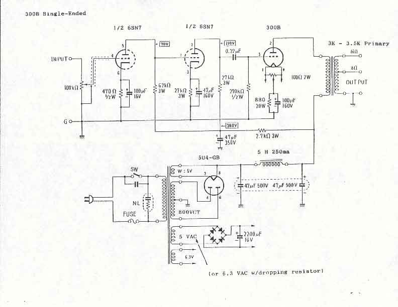
The voltage which will arrive at the 6SN7 driver stage is in this amp determined by the B+ (leftover terminology from days when tube radios worked off wet batteries--you don't want to know!) voltage for the 300B and the current the 6SN7 input tube will consume. We know this to be the plate voltage of approximately 350V plus the auto-bias for the grid of 72V plus the copper resistance drop over the primary of the already selected transformer (164ohms resistance, 72mA drawn) of about 12V which adds up to 434V.
In fact, the standard transformer we will choose, with the standard off-peak supply where I live in this amp delivers about 432V from the junction after the choke input filter. That's a lot closer to reality than many other calculations and rule of thumb expectations will deliver to most of our pretty, neat, clean numbers. That 432V is after accounting for 219mA of current consumed (144mA for the two 300B, 43mA bleed to stabilize the choke input filter, four 6SN7 sections each drawing an arbitrarily chosen 8mA for a total of 32mA, equals altogether 219mA).
Note the 32mA required from the power supply beyond the filter and the bleed resistor and the 300B supply. This 32mA will be drawn over the RC isolation filter for the driver stage. We could try to make this resistor very small to preserve the voltage but in fact there is another constraint, that we want to use 47uF or 51uF polyprops. A smaller dropper resistor would require a bigger cap to maintain the constant time base required in a good SE amp. Space and money requirements escalate very quickly when we start piling on polyprops. We are thus stuck with the 1K resistors for droppers which work with the polyprops we have chosen as cost and space efficient. The voltage available thus drops to 400V.
At this stage we can leave the power supply momentarily and return to the driver stage design.
Far from being a frustrating mess of conflicting requirements, once you sort out the method, iterative design becomes a powerful tool to help you understand what experienced tube designers mean when they say, 'Everything is part of the transfer function, including the power supply.' (They mean much more than this design compromise. We will get to it.)
At this point then in the design of our driver stage, we have four fixed points already:
1. The plate current of the driver for the 300B must not be less than 8mA.
2. The plate load is fixed at 27Kohms.
3. The supply voltage to the stage is fixed at close to 400V.
4. Therefore the plate voltage will be ((400-(27000*.008)) = 184V.
So all that remains within our control is to fix the negative bias voltage. On the transfer curves of the 6SN7GTB draw the horizontal 8mA current line, draw the vertical plate voltage line at 184V, draw the 27K loadline through the crossing and voila, that is your stage. Next read off, by interpolation between the grid bias curves, the negative grid bias you must arrange to make all this work, which is about -5.4V. (Remember, every point to the right of the 0V negative bias line is negative. It generally doesn't matter for our calculations whether the sign is rendered but it is respectful of the gods of mathematics.)
Check that between the design centre and the point where the loadline cuts the zero negative bias line there is 70V or more of plate voltage 'swing' on the plate voltage scale along the bottom of the schematic.
Check that at the chosen operating point the maximum permissible dissipation (quiescent current multiplied by plate voltage) has not been exceeded. Note on the spec sheet that the 6SN7GTB, a dual triode inside the same glass envelope, has different power ratings for using one half and for using both halves. We shall be using both halves.
You can draw the limits of the 4.6V maximum signal expected to arrive from the input stage as both positive going and negative going signals along the 27K loadline to the right and the left of quiescent point (0.8mA, 5.4V negative grid bias, 184V plate). You can calculate distortion at full signal and at the signal requirement for one watt with the information in earlier sections. But the 6SN7 is so linear, it is hardly worth bothering. If you insist, the only way to measure precisely enough is to work on your computer on a huge scale rather than on a printout.
The cathode resistor value is the voltage drop desired for the negative grid bias divided by the plate current, Vd/Ia, in this case 5.4V/.008A. A 680 ohm cathode resistor will do nicely.
The cathode resistor bypass capacitor of 82uF is specified by our shortcut that the product of the resistor value in ohms and the capacitor value in microfarads should be around 50,000 to provide bypassing to 32Hz, our chosen unattenuated low pass frequency. Or we can justify the choice by the concept of maintaining the same time constant through our amplifier. Even a 100uF capacitor will be acceptable if you cannot find one of 82uF; quality is more important than the precise value..
The coupling capacitor which links the signal from the driver to the power stage can be 0.22uF in conjunction with a grid leak resistor of 250Kohm, once more specified by our time constant. There is a more detailed discussion below.
Specifying the input tube
The 27K loadline specified for the driver also looks good here. I once again arbitrarily choose 8mA plate current as a linear place to operate the input tube.
The input tube is designed exactly the same way, with the voltage available after another stage isolation filter determining the plate voltage after the drop over the 27K load, and the chosen plate current of 8mA then determing the negative bias of 4V, which in turn determines the cathode resistor of 500 ohms.
Off the cuff, the cathode bypass capacitor can be 100uF. Sometimes I boost the input tube's cathode bias capacitor to allow for bandwidth losses further in the chain. Such losses are cumulative. Such boosting is received wisdom in multi-stage push-pull amps. Here we are in fact protecting the possibility of using a horn speaker, so I won't indulge.
Or, again, we could argue convincingly for making all the time constants in an SE signal chain precisely the same. It is your amp, so you can decide whether you want to make allowance for losses in the chain or follow the received wisdom on time constants.
The coupling capacitor to the next stage can be 0.1uF in conjunction with a grid leak resistor of 500Kohm.
All that remains to be decided is the grid leak of the input tube, which will also double as the input resistor or the load on the source.
Source impedance matching at the input
If you intend using a pre-amp, the input tube grid leak resistor must be specified with reference to the load requirements of the pre-amp.
In general, the lower the grid leak resistor of the input tube the better the bass response of the amplifier. In general, the higher the input resistance, which forms the load on the previous device in the chain, the better that device likes it. Tubes have a specified maximum limit of grid resistance for various types of bias arrangements, much lower for fixed bias than for cathode bias; a tube that for cathode bias might be permitted up to 0.5M ohm or 1M ohm for fixed bias will be restricted to half the lower value or less. Some small signal tubes, especially those intended for radio frequency (RF) work, can be a pain to make work with anything higher than a very low value of grid leak resistor. The designer must choose a compromise.
If you don't use a preamp but a line level source like a CD, the same expectation applies of the resistance the output 'wants to see'. Example: My QUAD CD player requires an input impedance of 'not less than 10Kohm', so an attenuator from 20Kohm up will do.
Note however that if you build an integrated amp with a volume control, the volume control is in parallel with the input tube's grid leak resistor. One solution is to use that part of the attenuator (volume control) between the wiper and ground as a grid leak resistor. The attenuator must then be so chosen that at any expected setting enough resistance will stand to ground, or additional resistance can be inserted in the attenuator's ground leg, an old trick to shift the volume control range here made to serve a second purpose.
We choose a 100K DACT stepped attenuator to double as the grid leak for the input 6SN7 and as the volume control and as the load on the specified source of the QUAD CD player.
Now we have a signal ciruit complete from source through volume control, input tube, driver tube, output tube, output transformer, loudspeaker. We cannot see the power supply as something beside it, of little importance, but we do already know a lot about the power supply still to be designed, in particular that it will deliver the required voltage and current while observing the desired time constant.
The circuit we have designed I call the T44bis 'Populaire' for reasons I'll make clear after we discuss a few tricky details we glossed over a bit on the way here.
More received wisdom
By the way, we are breaking another shibboleth here. It is also received wisdom that an amp designer should not use two tubes of the same tubes in adjacent positions or, even more rigorously, that he should not use the same tube twice in an amp. The reasoning is that no device is perfectly linear and therefore using it twice doubles up on its peculiar disharmonies a.k.a. distortions.
We have used the 6SN7 twice. The 6SN7 is an ultra-linear tube. Those who say it shouldn't be used twice claim a different reason: double the purity will create an acid sound that will rip your ears off. As far as I am concerned that is just grist to the mill of the euphonious added-harmonics argument. I like the crisp clear undistorted sound of two 6SN7 in a row. It is notable that in the Fi Primer, intended for beginners, JJ Morrison shows a design with two 6SN7, and Herb Reichert also published a design with two 6SN7 a couple of years after I first published this design.
However, it should be said that this design with two 6SN7 is more favoured by American audiophiles than British. The British, and the Japanese for that matter, generally like a warmer sound than the Americans.
For a ZNFB SE amp this topology of 6SN7>6SN7>300B>high impedance output transformer is about as pure as it gets. This is an elite of tube purity. Greater linearity it is not possible without sacrificing the KISS principle.
Any amp intended to be significantly 'better' on some other parameter than linearity will require expertise, machinery and money outwith the reach of most DIYers. As you will see when we proceed in the next section to the input/driver of the ultra-fi amp we're designing parallel to this one, I don't even try to improve on the silence and linearity of two 6SN7 in a row. Instead, on a subjective assessment of the quality of the sound I want, I refine the KISS principle to pare down the circuit and spend heavily to get a single tube of good linearity capable of driving a 300B by itself.
Specifying the coupling capacitors
Nor is the grid resistor set in isolation for later stages, as we have hinted above.
Any stage will be 3db down at the frequency
f1 = 1/(2*pi*C*R)
in which C is the coupling capacitor in microfarads and R is (Rg2 + ((Rp*RL)/(Rp+RL))), with Rg2 as the grid resistor of the next stage, and RL and Rp as the plate load and plate resistance of the stage under consideration.
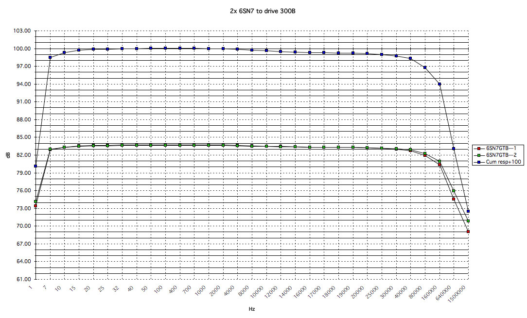
Now, one can mess around with this endlessly but I know from experience that I like the output at the second stages of a cascade of two voltage amplification stages driving 300B to be approximately 1dB down at 20Hz, which in turn means that each stage taken in isolation must have a -3dB (f1) point of just under 7Hz. Let's rewrite the formula to tell us what the value of the coupling capacitor should be in each
C = 1/(2*pi*R*f1)
After we substitute our numbers we discover the nearest standard value of capacitance is .22uF for the driver with the 250Kohm grid leak following and .1uF for the input with the 500Kohm grid leak following.
Our choice gives the cascade of two 6SN7GTB a frequency response curve 1dB down from the 1kHz reference at under 20Hz and just on 25kHz, a symmetry that appeals to my ear.
Bigger coupling caps will give better bass extension: 0.68uF will give an absolutely flat response all the way down to 20Hz though you will have to upspec the cathode bypass caps as well in order to enjoy the better bass. Good luck with finding speakers to suit!
If you intend using this amp with the Lowther horns for which we are building the KISS ultra-fi amp, the coupling caps should be halved to prevent deleterious high energy from bass below the free air resonance the Lowther drivers reaching speakers.
This amp is being designed to take its input directly from a CD player. If you use a turntable, you should ensure that there is a filter somewhere in the input chain to attenuate the high-energy bass signal drastically before it reaches the power amp, or you will hear your turntable being rude!
There is a voltage drop across the coupling cap but if the amp is being designed so close to its margins that it is worth calculating, the design is no longer conservative and the method is thus outside the scope of these articles. Those who insist can find the necessary formulae on p483 of F. Langford-Smith's Radiotron Designer's Handbook, 4th edition.
A few crosschecks to ensure good design
Generally, for good power delivery, we want a plate load resistor of at least twice the value of the plate resistance, and preferably larger. We check our design and discover that the plate load resistor of each 6SN7GTB at 27kohm is near four times plate resistance of 7.7Kohm: 27Kohm/7.7Kohm = 3.51.
Now that we have both the plate resistors specified as 27Kohm, we can check that they are smaller than the following grid leak resistors by at least a factor of four. They are, so no change is required.
When using common small signal tubes (the 6SN7 was very common c1950!) it is usually not necessary to refer to the spec sheets to discover if 500Kohm grid leak resistors are safe--almost all tubes specify at least 0.5Mohm maxima.
Theoretically there is no point of either power or distortion advantage in going much higher for a grid resistor than 4 times the value of the preceding plate load resistor. However, here we are protecting a time constant which plays a big part in producing an ultra-silent amp.
Check the midfrequency gain!
At this point you should check the midfrequency stage gain (Am) mathematically because it would be stupid to build an amp without enough oomph. In its simplest form, absent the following grid resistor, the midfrequency gain is
Am = (u*RL)/(RL+Rp)
where u is the nominal gain of the tube, RL is the plate resistor and Rp is plate resistance. Your answer should be between 15 and 16 (actually 15.88 but in real life these things are never that precise!) or about the same as 4.6/0.3 and 70/4.6.
If we're being pernickety:
Am = gm/(1/Rp + 1/RL + 1/Rg2)
in which gm is the transconductance of the tube. This sum is
Am = -2600^-10/(1/7700+1/27000+1/500000)
or 15.4 after we reverse the sign. Thus 0.3V *15.4*15.4 delivers a peak swing of 71V to the grid of the 300B, which is spot on target.
This example demonstrates one great advantage of conservative design. It delivers such grand margins that one never has to do the hard calculation when the easy one is to hand! The other two grand advantages appeal to engineers and audiophiles: an amp with such margins will of course last a very long time, and operating it on only part of its output curve naturally makes its response that much more linear.
The shortcut and the truth
Is that all there is to it?
No, not quite. A professional designer would make multiple other checks. Two of these, the slew rate current and the Miller Effect, are covered elsewhere in these notes.
We've been a bit politic with the shortcuts. Here are a few items that those who worry about such things can look up in the literature, the RDH being particularly good on such matters:
The resistance of the output transformer primary causes the plate voltage at our chosen operating point Q (on the loadline, at a particular plate current and bias voltage) to be less than that indicated by our graphical means of dropping a line perpendicularly from Q to the plate voltage. The dropline should in fact be of the slope -1/R' where R' is the primary impedance of the OPT, but the difference it makes is too small to bother about.
Another is the so-called 'rectification effect'. The second harmonic component of the signal frequency plate current (the same as the peak value of the second harmonic current) causes the static loadline of our simplified assumption to shift upwards to a new dynamic loadline which achieves maximum distance from the static loadline only at maximum signal. We could tediously draw it at maximum signal strength but it is irrelevant because in fact our conservatively specified amp will most of the time be operating at fractional powers. In this regard, an amp which is not conservatively designed will be incompetent in lacking adequate headroom (capability for handling high-voltage momentary or 'transient' signals such as all music possesses) and will offend aurally by clipping at crescendos.
Similarly, cathode- or auto-bias (the interchangeable technical names for the bypassed cathode resistor method we are using), cause a movement in the loadline, and a further angling of the dropline from the nominal operating point Q to the plate voltage baseline to a total slope of
-1/(R'+Rk)
in which Rk is the cathode resistor.
Finally, the curves of power triodes are usually drawn for DC filament supply. If AC is used, the same performance is achieved by increasing the grid bias by half the nominal filament voltage. This is done, if it is done at all, pretty roughly, the increase for a 2.5V filament such as found in a 2A3 for instance being commonly taken as 1.5V. We are operating, or should be, our tube too far from any natural barrier to bother about this one. Still, it's a nicety for showing off the depth of your knowledge on the newsgroups!
All of these factors cause the operating point, Q, which we notionally conceived of as fixed, to dance around dementedly, even if the jitters are often too small to draw confidently on the schematic because the scale is too minuscule to do justice to the tiny measures involved. With the margins of our conservative design cossetting us, we can ignore its antics.
Wow!
Thus at this point in the progress of a conservatively designed amplifier, an amateur could just design a power supply for his amp (coming soon to a theater near you) and build it. But I like to see on the computer how the amp will work before I commit expensive parts, and if one is going to the trouble to build a computer model, one may as well incorporate a few of the critical finer points whose tedious calculations are more expeditiously handled by the computer than by a man with a slide rule. I'll show you in a later section how to do this.
Without even breaking sweat, we have just designed a Real McCoy Type 44bis 'Populaire' which, when built right with the right components from the vendors listed on the schematic, will put your sound firmly into the high-end--if you give it enough beef in the power supply.
Why, you may ask, is this amp, elsewhere in these notes called just 'standard good' or 'T44' nicknamed the 'Populaire'? It is an adaptation of the base amp from the Modular Amplifier Series 300B I published in the mid-1990s. (Base in the sense of the cheapest recommended to DIYers; there was a stripped out T43 below, intended to be built with stacked photoflash caps available free from massmarket film developers in industrial waste bags of Ucutemout instant cameras.) Above the T44 there were about a dozen amps lovingly developed from it so that DIYers as they saved up could add a tube rectifier and much, much more iron, and proven audiophile parts (well, actually, some were cheap but had been found good by me on test). Unfortunately for all my hard work, DIYers who built my amps took to the T43 (a few, some for the gimmick value), the T44 (the vast majority) and the ultra-refined Types 49-51 (a surprising number of plutocrats with soldering skills). Even my friends, who I thought should have been more discriminating and flattering about the designs for a stairway of amps DIYers could build piece by piece to beyond ultra, simply crisply acclaimed the T44 as 'the best of the series'. At the time that brassed me off but time brings objectivity.
Today I agree with them: in that lineup the T44 was the standout value for money amp. The KISS 'standard good' amp is thus the dual mono T44 simplified to be the stereo amp T44bis and named 'Populaire' in honour of their sound judgement and the inescapable fact that it has proven the most popular of the series.
PS: Notice something I have hardly mentioned? Negative feedback: there isn't any in my KISS Amps. Here's why.
THE VOLTAGES IN THIS AMP WILL KILL YOU.
GET EXPERIENCED SUPERVISION IF IT IS YOUR FIRST TUBE AMP
All text and illustration is Copyright © Andre Jute 1997, 2005
and may not be reproduced except in the thread KISS xxx on rec.audio.tubes