
KISS 112
KISS 112
Choosing an operating point for a new design
Andre Jute
In electrical engineering theory, where all components are hogged out to a limit predetermined by their desired service life in the application under consideration, you would take the power required by your preferred speakers in one hand and in the other a list of only those tubes capable of giving the required output plus the longevity margin. Higher power tubes would not even be considered unless they were cheaper. In DIY audiophile practice we don't care much for the cost constraints of production engineering and our primary interest is in choosing tubes that will sound right with the speakers, or sound right on some other parameter. Thus the power we calculated so carefully is irrelevant. If we like the sound of a tube that makes less power, we can parallel two or several of those tubes. If a tube makes more power, even much more power, we can apply the extra capability to other desirable purposes, like reducing distortion and thereby making a more silent amp.
However, as I explained in an earlier installment, the choice is not as unlimited as seems at first glance. If you have your heart set on joining the ultrafidelista with a directly heated triode (DHT) amp your span of choices is not huge and your reasonable choices are pitifully few, and even fewer if like me you prefer designing with current production tubes rather than NOS. (Once I had to, for commercial reasons. Now I do it by choice, in order to leave NOS big DHT to those who think there is something special about them. I happen to think that many modern tubes are just fine.) However, you can triode-couple many pentodes for pleasing results. One of the first amps I ever built was a 6V6 triode-coupled SE adapted and developed from a Princeton guitar amp. Use what you can get and afford. EL34 and their little sister the EL84 can be ordered out of many general electronics catalogues--here is an
EL34 triode coupled single-ended design I built as a student amp. Think laterally. The 6SN7 is not only a superb driver but a 4.5Wpower tube you can parallel to make enough very clean power to drive sensitive speakers easily.
Back to the DHT. In fact, you don't start a design process like this without already having a tube in mind, even if only provisionally. The first tube in my mind whenever I start a new design is the 300B. It sounds good, it is long-lasting, it is available in a range of prices. Most of all, it is the only DHT which comes even near to the availability of guitar tubes like the EL34 and the EL84. Sure, I like Svetlana's SV572-xx even better but who will assure me of a guaranteed supply? 845 are grand but they are very big, very hot, and they don't run right under 960V operating voltage, which means a supply of over 1100V.
Thus I started The KISS Amp with 300B in the back of my mind, plus a lot of other high-quality luggage from various 300B amps I have built. At this point, having finalized the speakers and their power requirement (1.5W minimum, 3W absolute max) we can make other choices. The 2A3 is a well-reputed tube in that power bracket which even has the added attraction of 6.3V filament octal based version, the 6B4G, which could be a good cost saving and ease construction. I am somewhat underwhelmed by it, mainly because it does not live up to its billing as a cut-down 300B. A triode coupled EL34 will make the power without breaking sweat. Even EL84 will cut it.
For this project I shall stick to 300B.
There are two really good reasons for choosing 300B even for a newbie project. The obvious one is that it doesn't matter which tube I choose as long as the process is transparent, because the newbie who has all the facts can adapt the design to whichever tube he wants, so I may as well choose one of the tubes I have a huge amount of experience with rather than some cheaper tube that I have worked with much less often. The other overarching reason is that the 300B is an aspirational tube with a huge reputation. Eventually every serious audiophile gives a 300B amp a whirl of some kind, either by making a serious effort to listen to one belonging to someone else or by building one (or even buying one, ouch!). It follows that a 300B which can be built at any component level is a Good Idea because it can be upgraded over time.
ooOoo
You need a set of data sheets for the 300B. It is available several places on the net. Use Google.
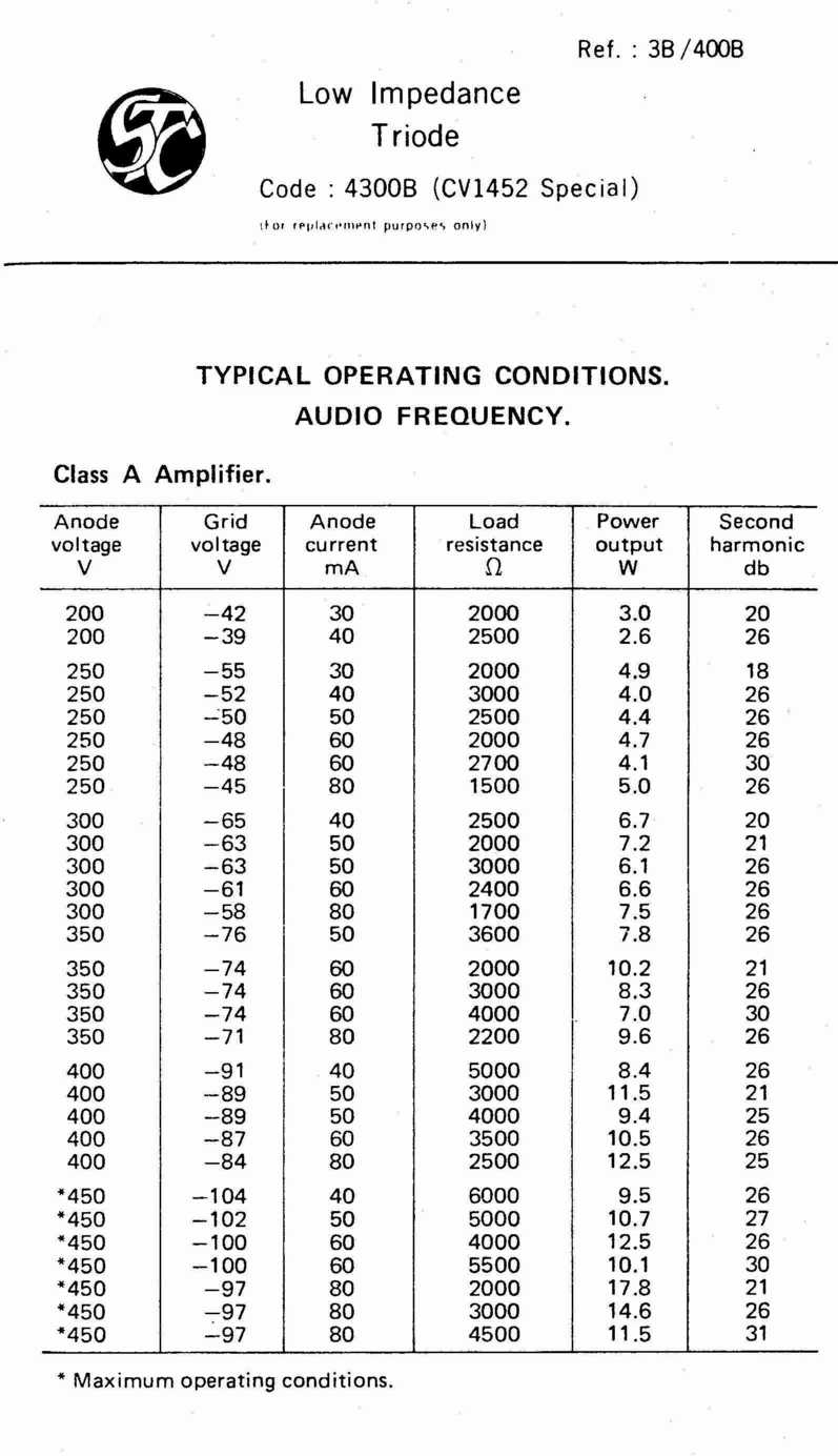
For your convenience I have put only the most commonly used of the famous STC 4300B data sheets on my site; these are generally the sheets to use with Chinese 300B.
112-4300b-1h.jpg 300B physical dimensions, standard and limiting parameters.
112-4300b-2h.jpg Typical operating conditions table, generic 300B.
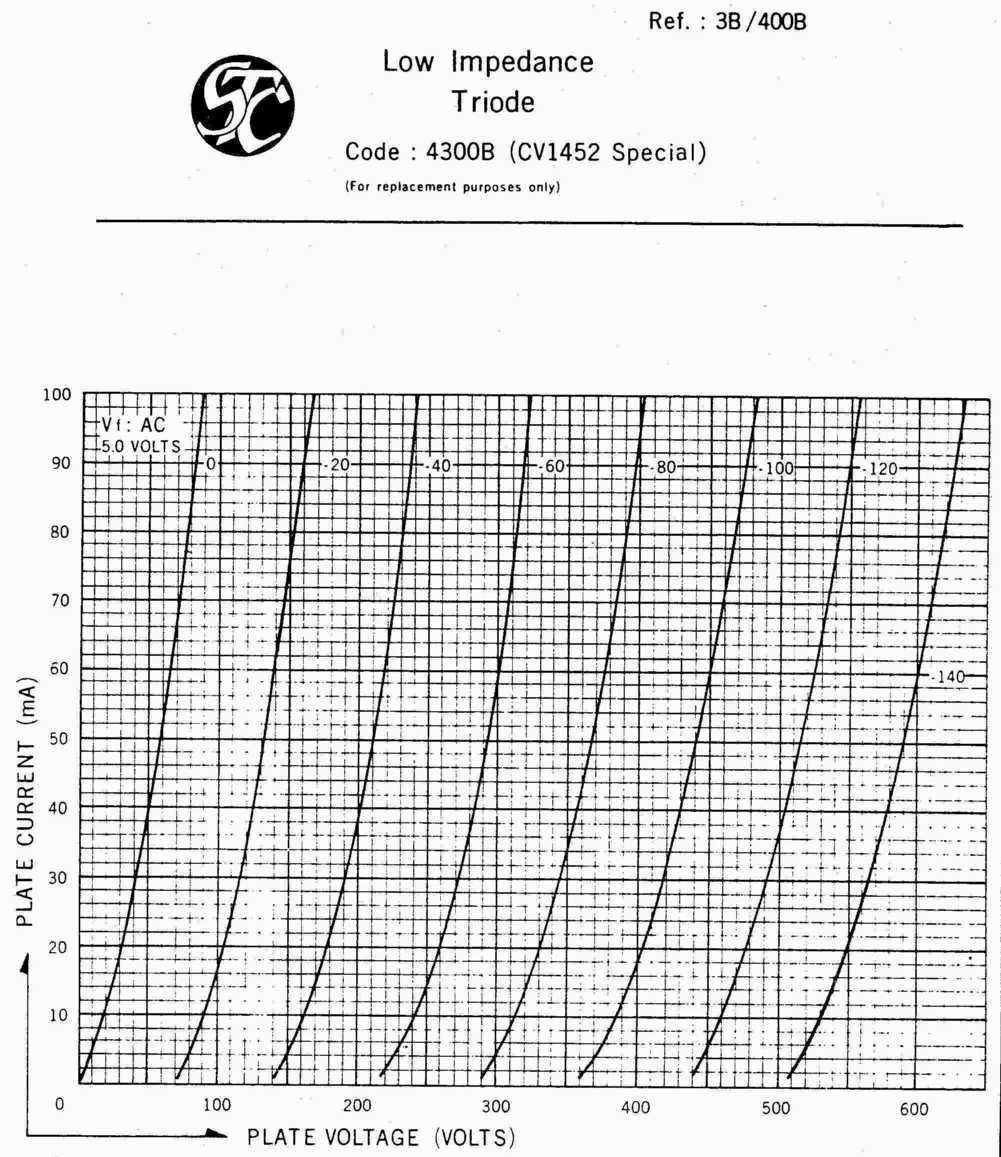
112-4300b-3h.jpg 300B Transfer curves: your Bible, Koran and pinup.
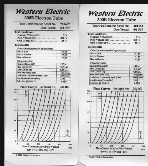
In addition there is
the individually-taken curves for the pair of WE300B I shall be using in The KISS Amp.
The data consists of the operating conditions for the fixed services of the tube like the filaments, specifications of characteristics like the nominal plate resistance Rp of the tube, recommended operating conditions for parameters over which you have control like voltage and grid bias, and so on. There will also be a set of graphs of which the most important will consume the rest of this article.
There are usually some warnings in footnotes to which you should pay attention if you are of a nervous disposition or poor. Two warnings are generally important for every tube: the warning about permitted variation of the filament voltage and the warning that maximum operating conditions are not intended to be usual operating conditions. Also mind the convention that not more than one operating parameter must be maxed out at a time. Whether the rest of the limits are important to an audiophile depends on the tube and its original purpose. Many tubes are grotesquely overspecified for audio use because they were designed for the military or the telephone company. The WE300A and B tubes were designed to be used in bank upon bank not for music reproduction but by the telephone company who didn't mind paying for a good tube if it saved the labor of finding and replacing a faulty tube. It is an intrinsically very sturdy tube. I use some from broken pairs and quads for shunt regulators and they just last and last.
AN ANALOGY
A tube is a sort of pump, which accounts for its British name of valve. A triode consists of three main operational elements (there are others, of which the most notable is the absence of air, the vacuum that gives the vacuum tube its name). The signal will be injected at the grid. Power to operate the pump flows into the plate, also called the anode. At the cathode a small outside motor pulls down the grid to make space for the signal, which is then squirted out of the plate at a much larger pressure. At this point it meets the primary of the OPT and is rolled along its slope into the sort of pressure (power!) the loudspeaker can use.
The power injected at the plate is called plate voltage, the signal is also a voltage (but of another kind called AC for alternating current), and the amount of voltage the external circuit element pulls down on the grid is called the negative bias voltage. These voltages will relate back via current to the power in watts required at the loudspeakers.
TUBE OPERATING CLASSES
It really is as simple as that. Every tube works that way, though some have so much excess baggage that it may take many, many pages to described the action.
However, though the analogy seems dynamic enough, it is really a static description. The moment the tube starts working it gets more complicated.
I want at this stage to eliminate one possible complication altogether. This is tube classes of operation. The question has already arisen with some of you, and will arise with all the minute you see the graphs in the data sheets: what happens when the signal is bigger than the negative grid bias? The exam answer is that it starts drawing grid current.
Grid current is an ultrafi baddie in the nastiest possible odour. Kondo-san, a giant of audio design, couldn't resist hogging out a little more power by letting his Ongaku run into grid current (technically called Class A2 Operation) and thereby made it less perfect than it might have been.
An ultrafidelista amplifier does not soil itself with grid current. It doesn't even come near it. An ultrafidelista amp runs in Class A1 under any and all operating conditions.
Once you decide that, you do not even want to know about Class B (horrid cross-over distortion), Class C (semi-permanent distortion) or class D (permanent distortion, not fit for human or animal consumption). Amplifier operating classes are of no further interest to you. If it operates outside Class A1, it is beyond the pale.
WHEN YOU HAVE DOWNLOADED THE DATA SHEETS...
Study the tables. Identify the main operating graph, which will have volts along the bottom, current in milliamps up the side, and lines at an angle which curve at the bottom. The lines are the negative grid bias voltage lines.
WARNING ABOUT DEVILRY
We will shortly arrive at a point where you will compare an answer you have derived from a graph with a table printed by that biblical authority, Western Electric. Oh, horrors, your answer will not match theirs!
Someone relatively new to valve design looking at, say, the WE 300B data can easily be baffled because his calculations show 2W of output power at a particular set of operating parameters while the iconic data sheet claims 6.7W.
Amazingly, it is more likely that you are right than that WE is right.
WE and STC (makers of the British 300B workalike, publishers of a widely used datasheet which is commonly applied to modern Chineses copies) were commercial organisations. They exaggerated, either directly or by implication, to make their product seem more than it was. We cannot at this distance see the exaggeration too clearly because it has become the accepted axiom of reference. It is as if you let Ford of Detroit write the new DIN PS standard!
Specifically, even in Class A, tube makers, engineers and radio designers accepted 5% distortion as the standard reference at which they measured full power. To a modern audiophile that is of course entirely unacceptable. Secondly, check those sheets. It doesn't actually say 'Class A' or 'Class A1'--that is merely another modern assumption. I suspect that when they took those power and distortion figures the grid had already been driven well into current. You are therefore calculating by a different standard assumption than the one they applied.
If you were to calculate where five per cent distortion will fall and then measure the voltage and current swing regardless of the fact that it extends beyond Class A and is asymmetrical, you will probably approximate their published measurement.
ON CHOOSING OPERATING POINTS
So, after studying the tables for a bit, forget them. Also forget whatever you've read about other people's operating points; some of them parrot WE without any investigation or thought. The curves are the only true authority.
You should download
and keep it open for reference. It is exactly what it says, an introduction to the power of the tube transfer curves. For now it can be a visual aid to see the placing and shape of the lines you will draw. Work on a clean copy of the relevant sheet you downloaded earlier.
Study of the tables will have shown you that a range of OPT primary impedances are suitable for loading the plate of the 300B. Let's arbitrarily pick 3K, a traditional, very common 300B load.
Lay a ruler on the current-voltage-negative grid bias (Ia-Eb-Eg) graph at the load angle of your output transformer, which is roughly -RL=deltaEb /deltaIa where delta means change and stands for the triangular symbol the net does reproduce reliably, and ignoring rectification effects (explained later) for the moment or for good if you are lazy. The lower turquoise line on my sample represents a ruler laid on the curves at a different load to the one you are working with. As a test, work out the primary impedance of the transformer represented by the lower turquoise loadline between 100mA and 560V on 112KISScurves.jpg.
The minus sign indicates that the line is angled from top left to bottom right. Since your OPT primary Z is normally fixed by what is available, the formula is more conveniently written as
-RL*deltaIa=deltaEb
which in English reads as "multiply the output transformer primary impedance in ohms by an arbitrary amount of current in amps to discover how much the plate voltage will move because of it". Thus if your OPT primary Z is 3000 ohms, multiplying it by 150mA or 0.15A, tells you the plate voltage will move 450V because of the 150mA change in its current.
Now along this line you can choose any operating point of voltage/current/grid bias at which the dissipation is not more than 40W (max for the 300B). Better to work on 32W or 80%.
You can draw a maximum power dissipation (Pdmax) curve as voltamp points (VA, which are virtual watts called apparent power): for the 300B if you calculate 40W/V (eg. 40W/400V = 100mA) for every 50 or 100V across the bottom of the page (the plate supply) and draw it on the sheet, that is accurate enough because you won't in any event go near max dissipation. Perhaps you want to draw 80% dissipation or 32W as well or whatever dissipation level you believe in. On 112KISScurves.jpg I have drawn the yellow line at 32W or 80% of maximum dissipation.
The next thing you need to understand about the data is that the curves are often only partially drawn. On the 300B graph we are interested in, for instance, the entire right hand side of the graph is left to your imagination because it was not originally an audio tube. So, when I refer to the middle of operating band or the design centre or quiescence, all theoretically the same point, in fact it will be marked much nearer the right hand edge of the page than the middle.
The operating point is a design centre value. When WE says the max plate V is 450, they mean at quiescence i.e. no signal. The quiescent point is usually near or on the halfway mark as the loadline (the impedance of the OPT primary) runs across the negative grid bias lines. It follows that in fact the valve is good to 900V at maximum swing even if you may not put more than 450V into it at the no signal condition, and given of course that you do not exceed the 40W maximum dissipation.
Note now that the response curves (negative grid bias lines) curl at their bottoms. You don't want to be there either: distortion. Also, the zero bias line is not a good place to be too near to, as many valves start drawing grid current well into the negative grid area. So you want to start operating your valve on the loadline somewhat to the right of the 0V grid bias line to ensure class A1 output. You want to stop operating it at a point before the response becomes non-linear. This point can be extended by sliding your ruler up while holding it at the same angle so that at any plate voltage you are using higher current and somewhat lower bias. Slide the ruler, still standing in for your loadline, until it touches your chosen dissipation level and note that at this point the distance between the zero bias line (or some line you have drawn to the right of it and parallel to it to distance your ears from grid current) and the furthest portion of straight, equidistant output curve (again, the negative grid bias lines) it touches is longer than it can possibly be at any lower point.
Now choose the point, normally tangent to your desired dissipation curve, halfway between the ends of this loadline, and there is your voltage at the plate and plate current, and your negative grid bias.
The negative grid bias you set and the plate voltage you supply, both of which are under your direct control, between them set the quiescent current. Clever, eh? There will be more semi-automatic benefits to our design and our sound from the way tubes work with audiophiles rather than against them.
We should pause here a moment. The voltage you must supply to the plate (for auto cathode bias, which is what we are assuming) is the sum of the plate voltage chosen above plus the negative bias voltage. The output at the smoothing filter of your power supply must be higher still by the voltage dropped over the copper resistance (this is a real resistance you can measure with your multimeter, not the same as the load impedance) of the OPT.
POWER OUTPUT AND DISTORTION
Calculate the true power output and distortion by measuring on the curves, extending them upwards as required because their cutoff at the top includes another implied and untrue assumption, viz that the tube is perfectly and symmetrically linear.
The output power is the product of the peak to peak voltage swing and the peak to peak current swing divided by 8. Peak to peak means you measure along the loadline (representing the OPT transformer) for both the positive- and negative-going sections of the signal, which is short of twice the negative bias by twice the distance you chose to remove the end from the 0V negative bias line. To repeat, this loadline is centred on the quiescent operating point or design centre you chose.
The 2nd harmonic distortion % is
((((Imax + Imin)/2)-Io)*100)/ (Imax-Imin)
where Io is the current at your chosen operating point. In Class A single-ended operation you can disregard third harmonic distortion; with this method it is not likely ever to get into your aural threshold because you will be able to see something is wrong by visual inspection of the curves long before you hear it.
It really is that easy once one finds the right tools to do the job properly.
ooOoo
Notice how, except to tell you to work with a traditional 3K OPT, I gave you very few numbers? I want you to do this by yourself for several good reasons beyond familiarizing yourself with the most important graph in your life as an audiophile. You will be horrified by some of the numbers you work out. You will ask, But can this be true about the great 300B? Can it really be that distorted?
Because it is so common (relatively speaking in ultrafi, not in guitar amps!) the 300B is a relatively easy tube to design with for the experienced, and SE amps are simple to build once someone else has developed a quiet layout. But the 300B does have its pitfalls for the careless and the ignorant. Now, while it still costs nothing, wallow in a bit of carelessness and ignorance. Do outrageous things to that sheet of graph paper. Burn up a virtual 300B at 60W. Choke it into submission with a 10K OPT.
Beyond this point knowledge will corrupt you with lust for the 300B sound. You have been warned!
THE VOLTAGES IN THIS AMP WILL KILL YOU.
GET EXPERIENCED SUPERVISION IF IT IS YOUR FIRST TUBE AMP
All text and illustration is Copyright © Andre Jute 1997, 2004, 2005
and may not be reproduced except in the thread KISS xxx on rec.audio.tubes