
At the moment single ended one valve has a 4k6 load, but I drew the above to see what PSE looks like but the opt’s are 2k ohm. This graph represents 4k because two EL34’s achieve double the power. So power out becomes 16 watts. Don’t ask me where the distortion ends up, but I expect that when you check distortion at the same power out, 8 watts it would be less.
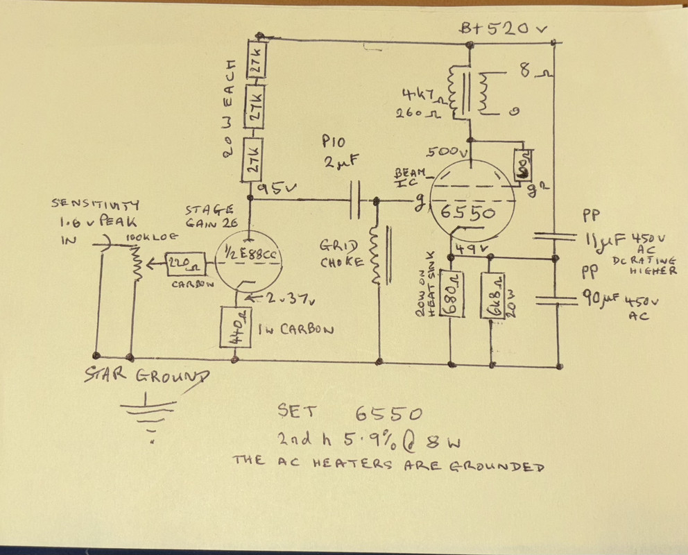
Interesting that the power out as drawn with one valve pretty well agrees it shows to use a 3k ohm load 348 Va 6 W 8% 2nd harmonic data in the Vade Mecum. Its a little anoying a lot of charts and data books dont specify what the Anode impedance is when triode connected. But the fact Vade Mecum suggests a 3k load, triode connected which implies a anode impedance between 600 to 800 ohm on the same lines of 2a3 to PX4. For the px4 a 600 ohm cathode resistor biases it. Though my choice of cathode resistor (which is per valve in the case of pse) is similar, right now Im using the 618 ohm. But the maths for the chart shown is 677 ohm precicely. The resistors are 680, so that will do and the 6k8 parallel is surplus to requirements now though not snipped off yet, as it is dual purpose to run with 6550 or EL 34, but I love EL34 more. 6550 is clinical, EL34 is emotional . I have shifted the operating point to the maximum voltage and set a dissipation limit of 27 watts. To allow for a little of the 8 watts permitted in the g2 to the 25 watts allowed from Anode. I could measure it in reality. But havent, by checking the current across the resistor connecting g2 to Anode. But haven’t. I’d be happy with ensuring the total combined current stays below 28 watts.
The power supply is capable of the current demand of pse. I think the 2k C cores should cope with the 116 mA. Hope so anyway. Time will tell.
I think I’ll keep this single ended version as built, and make another signal section for the pse, as the 2k transformers are existing that I made for the 6as7, about twice the weight as the r cores on single core like the r cores and Lundahls. I designed more primary inductance to make that planned amp at the time excellent at bass. But also interleaved 8 layers for good bandwidth. Made about 20 years ago.
There is no hurry 6 watts at home is OK even on the Q57’s but I do have to have the volume dial turned up to max. Which makes me consider putting a switch to switch out the 100k log Panasonic pot for grid chokes for such times when I’m alone.
Further experimental ideas. I found 6 hammond 150h for 8mA anode load chokes. Whilst I am totally happy with the sound of the amp, I may add three per channel to the resistor stack anode load in this amp. Just in case it helps the organic sound the gain and the bass. Probably in the present version. The beauty of inductors is as they increase in number series connected the capacitance reduces to half and inductance doubles per doubling of chokes.Nice!
"Two things are infinite, the universe and human stupidity, and I am not yet completely sure about the universe." – Albert Einstein

 so I can sell those, since EL34 much better sounding.
