My next task is to get the curves for plus grid using the safe method. Then plot a graph by hand.
Time permitted.
1619 Triode Curves.
-
Paul Barker

- Social Sevices have been notified
- Posts: 8998
- Joined: Mon May 21, 2007 9:42 pm
#16
"Two things are infinite, the universe and human stupidity, and I am not yet completely sure about the universe." – Albert Einstein
-
Paul Barker
- Social Sevices have been notified
- Posts: 8998
- Joined: Mon May 21, 2007 9:42 pm
#17
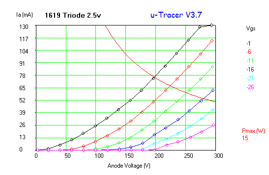
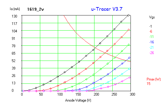
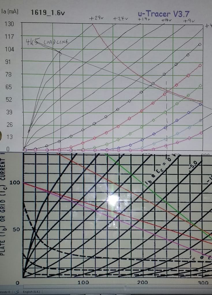
I traced the 1619 at various filament voltages in the first instance 2.5v 2v and 1.6v inspired by S. Bench pages many years ago.
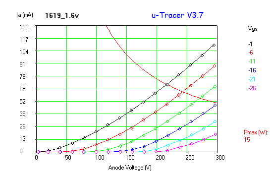
This helped me decide that 1.6v was worth trying. Then I had to establish positive grid volts. This was difficult. I did the +4v with a continuous +4v supply. Then I allowed the curve tracer to take over. It gave a silly +9v so I repositioned it by hand (not very well looking at it). +9v and above are all single curve traces using the Screen supply, printed off, held under the primary chart printed over light and drawn in.
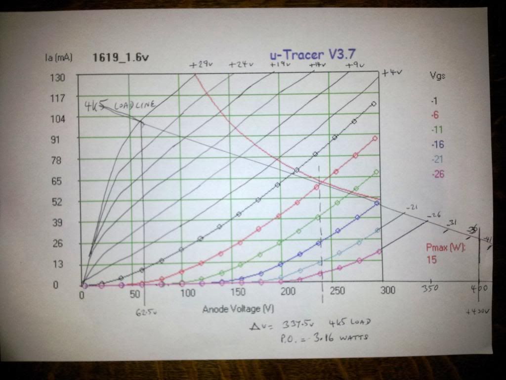
It is as clear as crystal to me that this valve is not suited to Class A1 use, it should either be used in class AB2 push pull or in class A2 S.E.
Looking at it again if you raise the B+ to 270v and bias at -11v you would probably get another 50v change in volts for 4 watts.
This helped me decide that 1.6v was worth trying. Then I had to establish positive grid volts. This was difficult. I did the +4v with a continuous +4v supply. Then I allowed the curve tracer to take over. It gave a silly +9v so I repositioned it by hand (not very well looking at it). +9v and above are all single curve traces using the Screen supply, printed off, held under the primary chart printed over light and drawn in.
It is as clear as crystal to me that this valve is not suited to Class A1 use, it should either be used in class AB2 push pull or in class A2 S.E.
Looking at it again if you raise the B+ to 270v and bias at -11v you would probably get another 50v change in volts for 4 watts.
"Two things are infinite, the universe and human stupidity, and I am not yet completely sure about the universe." – Albert Einstein
-
Paul Barker
- Social Sevices have been notified
- Posts: 8998
- Joined: Mon May 21, 2007 9:42 pm
#18
I re-proportioned Steve's curves to take the same perspective as mine. It demonstrates higher impedance slightly in this valve but there is higher mu from this valve.
Similarities are interesting.
4 watt A2 SE project is born.
801a will do this also, and sounds great.This is why I want to try it with oxide filament starved. You must not starve thoriated tungston of which the 801a consists. but then again the 801a may be inherantly more linear.
I don't however buy into the folk law that TT sounds better than Oxide per se. Not my experience at all.
As I demonstrated the Oxide filament 211 sounds clearly better than the TT vt4c. You would be right to point out there may be other contributing factors. But you can't say that in that case the valve with the TT filament sounds better.
Last edited by Paul Barker on Fri Jul 19, 2013 11:47 pm, edited 2 times in total.
"Two things are infinite, the universe and human stupidity, and I am not yet completely sure about the universe." – Albert Einstein
-
Paul Barker
- Social Sevices have been notified
- Posts: 8998
- Joined: Mon May 21, 2007 9:42 pm
#19
Told you I would have fun with the uTracer. I have barely started.
"Two things are infinite, the universe and human stupidity, and I am not yet completely sure about the universe." – Albert Einstein
-
Paul Barker
- Social Sevices have been notified
- Posts: 8998
- Joined: Mon May 21, 2007 9:42 pm
#20
In Strephies filament starvation article, for the 1619, the voltage was 1.4v and at 50v rms the THD was reduced from 5% to 1.1%. Stephie's explanatgion:
"So maybe we have explained the mystery; by starving the filament in DHT devices, the tube characteristics show a substantial region of not only constant mu, but constant gm and constant rp, thereby essentially removing all distortion causing mechanisms."
The curves of 3 different filament voltages a few posts above, in the negative bias region, demonstrate much cleaner less bunched towards the right curves in the filament starved case.
"Two things are infinite, the universe and human stupidity, and I am not yet completely sure about the universe." – Albert Einstein
#21
Wonderful measurements and analysis! This tell us so much more about the valve and how to use it!!! Many, many thanks for publishing your results 
I know I was very surprised at the results when I plotted the 6005 A2 loadlines and realised that if it was true to the published curves it was twice as powerful and twice as linear!
The starved filament stuff is fascinating too - a bit of a double whammy in our favour!
Just great stuff, Paul!
James
-
pre65

- Amstrad Tower of Power
- Posts: 21400
- Joined: Wed Aug 22, 2007 11:13 pm
- Location: North Essex/Suffolk border.
#22
If one had a filament module with an adjustable resistor it would be easy to try slightly different filament voltages.JamesD wrote:
The starved filament stuff is fascinating too - a bit of a double whammy in our favour!
James
The only thing necessary for the triumph of evil is for good men to do nothing.
Edmund Burke
G-Popz THE easy listening connoisseur. (Philip)
Edmund Burke
G-Popz THE easy listening connoisseur. (Philip)
#23
Good idea, why dont you design one and then we can all use them.If one had a filament module with an adjustable resistor it would be easy to try slightly different filament voltages. Wink
Whenever an honest man discovers that he's mistaken, he will either cease to be mistaken or he will cease to be honest.
-
pre65
- Amstrad Tower of Power
- Posts: 21400
- Joined: Wed Aug 22, 2007 11:13 pm
- Location: North Essex/Suffolk border.
#24
Tentlabs, Rod Coleman and DIY hi-fi ones all do, and very useful they can be.Nick wrote:Good idea, why don't you design one and then we can all use them.If one had a filament module with an adjustable resistor it would be easy to try slightly different filament voltages. Wink
Now you all know I could not design something like these, but the Mike H design from a few years ago was very good, and from memory that had an adjustable resistor. I must dig that out for a future project.
The only thing necessary for the triumph of evil is for good men to do nothing.
Edmund Burke
G-Popz THE easy listening connoisseur. (Philip)
Edmund Burke
G-Popz THE easy listening connoisseur. (Philip)
-
Paul Barker
- Social Sevices have been notified
- Posts: 8998
- Joined: Mon May 21, 2007 9:42 pm
#25
It is a workable idea Phil. In my case I'll just use AC it is a very low voltage, so you can just tag a winding of your own onto a Torroid and you can centre tap the winding for the cathode take off.
It also occurs to me that you can create the same hum in yuour driver valve. Scenario is you have a dht output valve with centre tapped filament. Your dht driver has a hum pot. Adjust driver hum pot for no hum at the loudspeaker. that may involve creating hum in the driver. The frequency is the same and the noise on the audio chain is 180 degrees adrift, which is where the cancellation comes from.
You could wind a few extra turns to select your voltage but for me starved is what I want.
That M7 doesn't look like a lot of use though! I may have the only pair of anyone I know, shame it wasn't a version of the AD1 yet undiscovered! Hay ho. I do have a single AD1 anyway. The list of valves yet to test is endless.
"Two things are infinite, the universe and human stupidity, and I am not yet completely sure about the universe." – Albert Einstein
-
Paul Barker
- Social Sevices have been notified
- Posts: 8998
- Joined: Mon May 21, 2007 9:42 pm
#26
Thank you James, makes the experimenting all worthwhile. those lines if they came from the same machine at the same time would be correctly spaced around the 0 volt point where my artistic positioning of it was poor. the spaces either side tell us the valve is linear. Along the lines of 211 and 801a. But also those little 7 pin valves are excellent.JamesD wrote:Wonderful measurements and analysis! This tell us so much more about the valve and how to use it!!! Many, many thanks for publishing your results
I know I was very surprised at the results when I plotted the 6005 A2 loadlines and realised that if it was true to the published curves it was twice as powerful and twice as linear!
The starved filament stuff is fascinating too - a bit of a double whammy in our favour!
Just great stuff, Paul!
James
In my case I am going to need a very low impedance powerful driver. I may just go for broke and use parallel 6as7 CF direct coupled. The hum cancellation will have to pass on through it from a DHT voltage amplifier stage. I suppose as the 6as7 CF is such an easy load it isn't beyond the realms of reality to use that Russian DHPentode MArk is using with sufficient gain that can pass on the filament hum. I have some anyway and I Loctal bases.
"Two things are infinite, the universe and human stupidity, and I am not yet completely sure about the universe." – Albert Einstein
-
Paul Barker
- Social Sevices have been notified
- Posts: 8998
- Joined: Mon May 21, 2007 9:42 pm
#27
Of course like your little 7 pin valve the 6V6 and the 6550 triode connected have some official positive curves.
"Two things are infinite, the universe and human stupidity, and I am not yet completely sure about the universe." – Albert Einstein
-
Paul Barker
- Social Sevices have been notified
- Posts: 8998
- Joined: Mon May 21, 2007 9:42 pm
#28
Trying out the new GUI demonstrates the screen supply not predictable at these low voltages as Ronald anticipated.

The corresponding A1 curves Cut and paste them together if you are able with photoshop?

Something isn't right. This is the trace which should m,easure grid current but it is measuring anode current.

Sorry it was user error, I selected the wrong Y axis option. See below.

So we can now gather extremely usdeful grid current data. The lines aren't reliable you have seen my excellent lines in earlier posts which show the valve is linear in A2. All we then need to know is the grid current so we can design a suitable driver.
The new GUI is a helpfull progression in the functionality of the present uTracer. I can't see it going further without a different add on board to sort out low voltage positive supply capable of feeding a load. Perhaps Ronald could implement an add on or it may be too difficult to integrate. Probably the latter as the brains would have to be reprogrammed as well as an add on board.
If you look at my previousl;y measured A2 curves you will see that you wouldn't be operating below 50v anode voltage so the grid current should remain managable.
The corresponding A1 curves Cut and paste them together if you are able with photoshop?
Something isn't right. This is the trace which should m,easure grid current but it is measuring anode current.
Sorry it was user error, I selected the wrong Y axis option. See below.
So we can now gather extremely usdeful grid current data. The lines aren't reliable you have seen my excellent lines in earlier posts which show the valve is linear in A2. All we then need to know is the grid current so we can design a suitable driver.
The new GUI is a helpfull progression in the functionality of the present uTracer. I can't see it going further without a different add on board to sort out low voltage positive supply capable of feeding a load. Perhaps Ronald could implement an add on or it may be too difficult to integrate. Probably the latter as the brains would have to be reprogrammed as well as an add on board.
If you look at my previousl;y measured A2 curves you will see that you wouldn't be operating below 50v anode voltage so the grid current should remain managable.
"Two things are infinite, the universe and human stupidity, and I am not yet completely sure about the universe." – Albert Einstein
-
Paul Barker
- Social Sevices have been notified
- Posts: 8998
- Joined: Mon May 21, 2007 9:42 pm
#29
OK here is the grid current for the previous A2 cdurves I drew by hand.

Which means for practical purposes we need to stop at no less than +75v anode volts unless we want to use a mosfet driver which would be anathama to me.
So on the above plot use a 3k5 loadline and you intersect the maximum grid volts at +75 anode volts, while kissing the max dissipation. That is your load! It is almost like drawing pentode load lines, where the lower load makes for the better optimum. We only discovered this due to the uTracer's ability to show us the grid current. It is a fantastic tool
I haven't stopped having fun yet!
"Two things are infinite, the universe and human stupidity, and I am not yet completely sure about the universe." – Albert Einstein