
KISS 191A
KISS 191A
miniGainBrick Zip LM675
by Andre Jute
Audiophiles often wonder if it possible to get 'that tube sound' with inexpensive solid state devices. This two-part article is about a partial journey in that direction, with a few hints for experimenters who want to proceed beyond the point where I stopped. The article is also of interest to those with some technical training who wonder what the constituent parts of 'that tube sound' are. The short answer is, yes, there is something in it and it is not all in people's heads.
It will be helpful to have these illustrations from
open on your screen:
KISS 191C mGBschem.jpg The opamp circuit for the miniGainBrick Zip LM675
KISS 191D mGBmatr.jpg A layout suggestion for the miniGainBrick Zip LM675
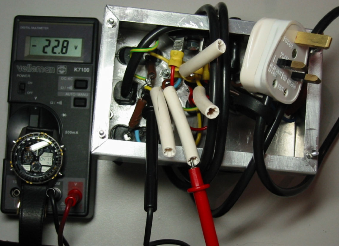
KISS191E NoBleed.jpg Living dangerously!
Introduction
I built the first version of this amp long before there was a Gaincard and Gainclones. It was suggested to me by, and the name comes from, a throwaway remark in correspondence from Nelson Pass (who is of course not responsible for any electronic or other horrors I commit in this article), about the gainblocks or tubed opamps that were used in days of yore by engineers to build large networks. I looked into it casually for a little light history-as-entertainment and then forgot about it. Later I discovered that many transistors are so antipathetic to my magnetic personality that they die if they come within inches of me even were I covered in a huge antistatic phophylactic. At this point I started looking into the more robust opamps and the idea of the gainblock blended with my interest, from tubes, in the sonic advantages of very simple amplifiers.
The Gaincard/Gainclone hullabaloo about minimum parts count is sometimes amusing. An opamp is not a single component, not by some magnitudes! Bare the opamp is, by valve standards and by the best hi-fi design standards in silicon too, a pretty nasty piece of excrement. Check the circuit of the gubbins on any opamp's spec sheet. The Gaincard maker doesn't count the switched attenuator at all, nor the components of the power supply. Despite this, potato-heads have been building tube amps with a lower parts count including the power supply for decades. (I'm playing a 417A single-tube amp as I write this. By the Gaincard method of counting, it has three components altogetherÉ)
But the opamp has its place and there is no reason that even in high-level audio it should not be an honourable place. (For a start, opamps offer less chance of driving you blind soldering one opamp than its hundreds of separate componentsÉ) I know from experience in both CD DACs and power amps that an opamp can be made to sound surprisingly like hi-fi with only a little thought, and it can be made into a star turn if you are willing to go the distance. Whether in the end the result is worth the effort--or, surprisingly, the cost by the time one succeeds--is another matter for those of us who find a tube amp as quick and easy to build as a silicon amp. Meanwhile, let us start where the opamp is a cheap and quick experimenter's component.
First we'll knock up a quick opamp amplifier that you can use over the holidays if your main amp suddenly gives up the ghost. Then we will see about making it sound like a tube amp.
Which opamp?
We're talking here strictly about the heftier power opamps. What is under consideration is a linestage amplifier to be driven directly by a CD player so that it's sensitivity will be 2Vrms. There is a lot of talk about this opamp and the other in the audiophile community's gainclone niche but in fact it doesn't matter which of the suitable opamps you choose. What is important is how the components around the opamp are implemented. The only key requirement if you want the best out of your opamp is that it should have a hefty current capability unless you already have sensitive speakers. If you do not intend staying with me all the way to Class A operation, then even that requirement can be relaxed.
I like working with the LM675T for no better reason than that I had a few in my junkbox when I started on the opamp road. It is sturdy, well-enough specified for audio experimentation, and cheap for what it offers. It also sounds surprisingly good even in a cheap, simple, quick knockup. If you restrain the power supply to 15V peak, you can use most other power opamps in these circuits, though when we get to the constant current device you should take care not to exceed the ratings of whichever opamp you substitute. Newbies should stick to the 675 for now because it is very forgiving.
The paradigm
We are not trying to make an opamp into a Krell. It may or may not be possible but it would be tiresome and more expensive than just buying a Krell. Of course, no one in his right mind will buy a Krell either when there are so many similar-measuring amps for a tenth of the price but even at a tenth of the price it is a pastime for madmen to enter a single-chip amp into the vanishingly-small THD stakes. I repeat, this is not about building another low-measuring amp for meterheads.
Instead we want to know:
1. Whether an audiophile amp, or a close approach to it, can be made with an opamp, preferably quickly and economically. A modest footprint to go with low cost would be rather jolly too.
2. Whether it is true, as some claim, that an opamp sounds like a tube amp and, if not, whether it can be made to sound like one.
The basic design
We start with a specsheet cookbook non-inverting design. If you're a near novice at opamp design and my circuit seems to you to have pieces missing, that is because I've thrown off the zobel as surplus to requirements for audiophiles and made the volume control double as the input resistor. After that I merely changed a few values to reduce the gain to sane levels so as not to exceed maximum ratings.
Note though that there must be an input resistance of some kind or otherwise the opamp will refuse to work as it will have no voltage reference. The leg of the volume control to ground ties the non-inverting input pin to a reference, 0V. I picked a 50K pot so that there can always be at least 10K to ground, the minimum load my Quad CD player expects to see.
Most opamps require voltage gain of at least 10 to work at all. The 1K2 resistor to earth and the 12K feedback resistor form a voltage divider which sets a gain of 11. Lower values, as long as the ratio is maintained, give lower noise. I just chose these resistors from my junkbox.
The power supply
The stiffer your power supply, the better, goes the audio mantra, at least in the majority of the silicon world. But many alternatives have loud enthusiasts, some are significant, and some are honoured by tradition and practice. The Gaincard/Clone paradigm is for a sagging supply that would disgrace a guitar amplifier, caps of 1000uF and so on. I tried it and hated it. That's odd as generally speaking I like my tubes fast, so on tube rectified, choke input supplies I usually work with 50uF caps, and like them fine. The Gaincard/Clone guys took over the argument apparently without sufficient thought. On an opamp that entire approach simply doesn't work. An opamp isn't a linear device like a tube. An opamp requires a reasonably stiff supply even in class C, which is pretty near where it works, certainly in class B (where it is claimed to work), definitely in class A/B (where we might intend to make it work). Only in Class A, which draws constant current, does the power supply become less of a bother (it either has the current you set or it hasn't, in which case it is instantly clear that you must start again). True Class A operation with a power opamp is however fraught and expensive to achieve.
After much experimentation I settled on 10,000uF caps as the lowest rating which is not aurally offensive in the result. You should experiment. You may like 20,000uF. But I think most people will agree that by the time the supply is smoothed by 50,000uF, the sound is pretty characterless, chilling even; if you want the despicable sound of a regulated power supply, then build a regulated power supply.
The 675 is rated 60V peak to peak, 3A, 30W. I chose my toroidal power supply for the version pictured because it fit the 4x4in Hammond box I first had this amp in; I soon transferred it to a 4x6in box to get the caps and power supply on the same side of the box. 36Vct 120VA is overkill for me because I own horns among several pairs of sensitive speakers, so that a handful of watts is plenty for me. But everyone else should use at least a 40Vct 150VA power transformer. And if you intend to use Class A with insensitive speakers, 300VA will look right handy.
My 36Vct tranny gives around ±25Vdc unloaded and from 40Vct you should expect around ±28V. We can work back to see if the transformer will handle the job. The load is the speaker which is 8 ohms. The 675 is rated 30Wrms when correctly heatsinked so the sum is ((SQRT(30x8))x1.414) which comes to 21.9Vdc, which is about what we would expect our power supply to deliver under load.
Remember that an opamp cannot handle a signal larger than the supply voltage.
I used a 35A dead-bug legs-in-the-air rectifier and bolted it to the ali case for a heat sink.
You will of course correctly arrange a quality on-off switch and a properly rated fuse on the input side of the power transformer.
Notice a missing safety device on the circuit. I haven't put a bleeder across the power supply output but you may wish to consider that 10000uF caps can give you a nasty jolt, or melt the tips of your pliers and screwdrivers. Check how little the voltage has fallen on the DMM in 3 hours 4 minutes by my wrist stopwatch (digital window, the analogue hands are parked at midnight so you can see the stopwatch). Without the bleeder and with no other devices attached, the power supply takes 24 hours minimum to discharge.
Construction
The 0.1uF caps should be as close to the opamp pins as possible. If you are obsessive you can get a surface mount 12K resistor and solder it right across the opamp pins. It makes very little difference because in any event even a semi-'fast' power supply will be filthy.
I show a matrix board layout for the signal section. There are six tracks per channel in order to keep the signal and power grounds separate. By using a twelve-track piece you can build a stereo amp with a PCB mounting pot included. Whenever I build a version of this amp I build two boards to lessen the risk of burning tightly packed components and to preserve my expensive stepped attenuator. The photographs show how component leads are used as offboard terminals. Note the separation of grounds between power and signal. Physically this scrap of matrix board should be mounted so that leads offboard to the input, output and grounds are kept short.
Heatsink!
Do not ever, under any circumstances, operate high power opamps without adequate heatsinking even for a few seconds. I get away with bolting my 675s to a small box because I use horns and operate the opamps rather moderately. Be sure you understand that in the next step, when we take the 675 into Class A, the energy dissipated as heat will increase substantially, up to half of the capability of the 675 or 1.5A if you really take it to the limit, and be constantly on. That is what Class A means, that the current to the device is never cut off. Class A is also only 25% efficient as compared with 50% for Class B. The heatsinking requirement accordingly increases geometrically.
If you divide 50 by the temperature rise of a device in degrees Celsius per Watt and square the result, you arrive at the required radiating area of the heatsink in square inches. Here it is again:
Sq inches of radiating area = (50/degrees Celsius per watt)^2
That is the very roughly the additional number of square inches of surface radiating into free air (not counting the inside of a box or the backplane of the heatsink to which the fins attach) you require to add to preserve the opamp's life after you have already made the box big enough (or added enough heatsinking) to remain at ambient temperature regardless of the demands of the other components inside.
I suggest that you don't start experimenting with opamps or any other power transistors until you have given yourself a thorough grounding in heatsinking requirements. If you don't, those cheap-looking transistors will suddenly start to mount into big monthly bills from your transistor-pusher.
Basic miniGainBrick Zip LM675 on test
So does it sound like a hi-fi amp? Yes, it does. Forget that it cost only fifty or sixty bucks to this point. It sounds far better than the sort of high-street amps you can buy for a few hundred. If it does not quite match my upmarket solid state and tube amps, it is not embarrassed in their company either. The first time I heard this amp I was amazed.
Is it truly hi-fi, defined as one's long-term opinion after the first flush of gratified surprise wears off? That depends on your experience and expectations. In my listening room it won't make the final cut. But then gear that costs tens of thousands and is highly thought of elsewhere routinely fails to make the cut here. But that's a false comparison. The key is how far a cheap little opamp can stay with the big boys, and that is an amazing thing. (It probably proves that the big boys, both silicon and tube, are way beyond too good for their own good!)
Does it measure really well? Yes it does, once you stiffen the power supply enough to kill the appeal of the sound. Let's be blunt: an opamp depends for its euphony on its artifacts. We have already discussed why it should not be viewed as a shortcut to another soulless silicon amp.
What's the explanation of the apparent anomaly? It's simple. The 675 is a push-pull amp operating on the verge of Class C all the time. Class B is bad enoughÉ The THD is tiny by valve standards, and can be improved by beefing up the power supply as I've said, but the odd harmonics one would expect are there, and switching noise and crossover distortion are subliminally present and a nuisance. You don't know those things are there until you remove them. Then it becomes clear why you felt, without quite being able to put your finger on it, that in the longer listening term this little amp won't stand up to the big boys.
In that regard it does sound a bit like a tube amp but not the most desirable tube amps, not say a 300B operating single-ended on the flattest part of its transfer curve and without any negative feedback whatsoever. What the 675 sounds like in this mode is more like a lotsaKT88/6550 PP amp before the developer applies the final 3dB of feedback to give it impressive THD numbers. There are some of us who think that the lotsaKT88/6550 PP amp sounds like shit with the recommended feedback, better with 3dB less (just like a 675!) and that with minimal feedback it sounds very much better.
Check it for yourself
At this stage you can measure your LM675T opamp amplifier and discover for yourself by varying the elements we can control--gain, input voltage level and smoothing--that the key element which varies the sound is the spectrum of distortion rather than its absolute level.
You can also test the surprising quality of the miniGainBrick Zip LM675 by playing it under the counter for unsuspecting visitors while ostentatiously leaving an expensive amp glitteringly switched on but without input or connection to speakers.
Can we make it sound more like tubes? In the next article at
we'll try. Go to KISS 191B by Andre Jute.
THE VOLTAGES IN THIS AMP WILL KILL YOU.
GET EXPERIENCED SUPERVISION IF IT IS YOUR FIRST TUBE AMP
All text and illustration is Copyright © Andre Jute 1996, 1999, 2004
and may not be reproduced except in the thread KISS xxx on rec.audio.tubes