By the time we come to design the driver stage of the ultrafi 300B amp there are so many hard points settled by the process elsewhere in the amp that the stage almost designs itself. Let us look at some of those hard points.
For historical reasons I decided on:
—a triode
—a Western Electric tube
—a single tube to do duty both as input and driver
—a 300B output tube which has a particular signal voltage requirement
All of this together fixes the input tube to a choice between the 417A and the 437A, which, given their relative availability and price is no choice whatsoever: the 417A is as WE tubes go inexpensive. Choosing the 417A is no hardship: it is a gloriously musical tube, a little wonder.
For reasons of taste I have chosen to use:
—a tube rectified input, which drops much more voltage over the diodes than silicon rectifiers
—a choke input power filter, which requires two chokes rather than one, so doubling the voltage drop in the filter, which further requires
—a big bleed because swinging chokes are not available these days; I would anyway want the big bleed for stability and safety
For reasons of common sense, aesthetics and cost, I have chosen;
—to buy my power transformer the same place as my output transformers
—all of that fixes the voltage available before the power isolation filter for the driver to 396V
From consideration of the necessary slew rate current and the Miller effect, I want to put a good deal of current on the plate of the driver for the 300B. Experience leads me to the same conclusion: high current is a club to linearize even recalcitrant tubes and the 417A, an RF tube, is not among the best behaved, though it is linear enough. But I selected it for its sonic qualities (if linearity were my only concern, I would have chosen the 6SN7 which itself sounds uncommonly fine.) So we have,
—high current; from experience 20mA is pretty linear though the hardliners prefer 24mA
—I need high current in any event because there will as a matter of principle be zero negative feedback
For sound sonic (hee-hee) reasons, I want battery bias on a 417A used as a driver. Remember, we are coming to this KISS ultrafi amp from the KISS standard reference of 6SN7>6SN7>300B>high impedance, an ultra-silent amp. While we are satisfied that we can back away from that perhaps overhigh standard a little, there is no call recklessly to embrace noise. I despise regulated power on the filaments of high-class amps for the bleached out, lowest common denominator sound it produces. (One of the reasons those big American amps sound like silicon is because they use beautifully designed regulated power supplies.)
Battery bias is one way of avoiding noise. It eliminates a major sound-shaping element, the cathode bypass cap, leaving us enjoy the sound of the 417A unadorned. The bass boost of fixed bias can be used by the selection of other
elements to shelve and tilt the driver-output tube transfer curve just so.
—battery bias fixes the quiescent or zero-signal operating point at 2.4V because that is what we can get ni-cad batteries for, 1.2V being too little and 3.6V taking us outside the tube’s permitted parameters (too much voltage on the plate—check the Eb-Ia-Eg curves)
At this point we thus have a tube operated at 20mA (arbitrary) and –2.4V (battery availability) and 175V on the plate (read off the transfer curves). 6K8 is conveniently close to our preferred multiple of four of the 417A’s plate resistance of about 1750--1800 ohms. All that remains is to calculate that a 6K8 load resistor will drop 136V at 20mA and now we know the power supply must deliver 311V at the takeoff for the driver.
The grid leak resistor of the tube following, the 300B, which forms part of the load on the 417A plate, thereby becomes a response-shaping element in precisely the same way as its associated coupling capacitor (with which it forms an HF filter). For the time being I shall merely tell you the grid resistor is 47Kohm and the coupling capacitor 0.1uF because we want matching time constants on the RC filters to the grid of the 300B and to its cathode. In a later chapter I will show how I deliberately used these two elements to shift and tilt the transfer function of the 417A/300B combination, what the pretentious call distortion cancellation; they’re in for a shock in just a moment...
Remember what I said about the relationship of wu to the swan? The way all this falls together so tidily has nothing to do with luck and a great deal with years of hard work on drivers for 300B over more than a decade.
The only remaining design decision is the value of the stepped attenuator across the input. The QUAD 67 CD player I favour demands to see at least 10K from the next device in the chain. But the 417A, which never stops reminding the clumsy that it is an RF tube, doesn’t like more than 10Kohm attached to any part of it. The compromise I choose is a 20K DACT stepped attenuator with very short tracks (it is built with surface mount resistors) plus a 220 ohm grid stopper soldered right to the socket pins of each of the four grid inlets of the 417A. (Use the centre pin of the socket for a common input end.)
Now we have a complete signal section for The KISS Amp 300B "Ultrafi" from volume control through driver, power tube and output transformer to loudspeakers. By now the power supply is essentially designed by reference to the parameters guiding the signal section; we shall discuss the general principles of the power supply in another chapter.
***
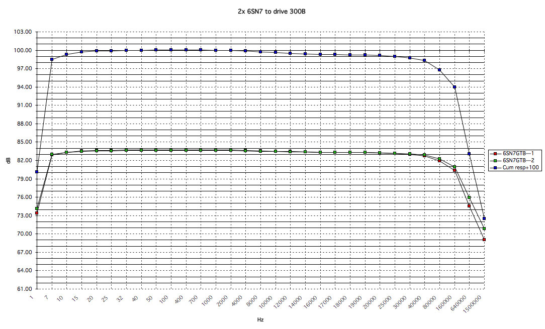
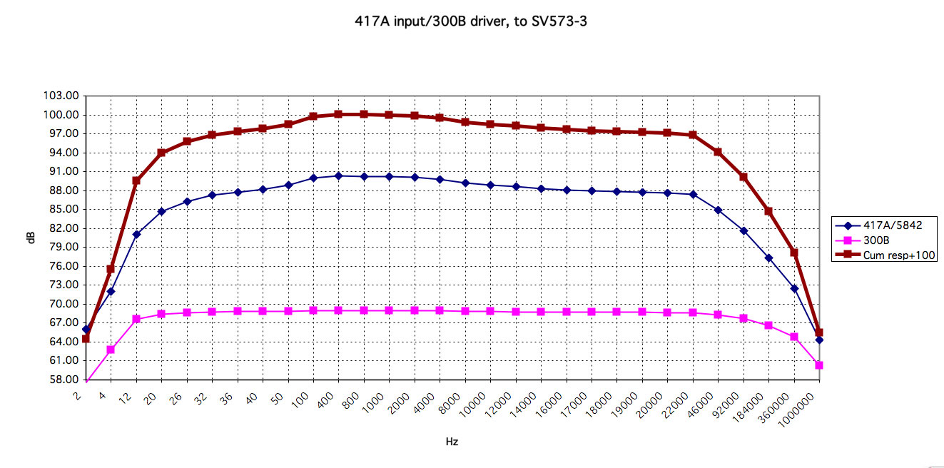
At this stage you may compare what I have done with the transfer function in the audio band with the standard reference amp of 2x 6SN7 working with 300B to what I have done with 417A in the Ultrafi working very substantially against the linearity of the 300B. When it was put to me by someone, who hadn’t yet seen the schematic for the circuit, that I would of course use the 417A for harmonic cancellation on the 300B, I burst out laughing. A 300B that requires linearization is incompetently implemented.
Make no mistake. I deliberately used the superb warmth of the 417A to subvert the blameless linearity of the 300B.
I did it only for a little way, and very selectively, of course, so you might say I did a reverse harmonic cancellation job.
There are several good reasons for what I did. First, I wanted highish and very quick rolloff below 36Hz to protect my expensive Lowther drivers fitted to horns because horns simply don’t load the driver below the fundamental resonance. This in turn requires that the top end be very carefully limited perceptually to balance the response around 700Hz or 1000Hz; this is a psychoacoustic matter with no electronic justification.
Then I went one step further and tilted the system response so that, instead of a sharp peak in low presence range like most SE amps (the source of the silly myth that SE amps must necessarily possess "added euphonics), there is a shelf that runs from 36Hz to 17kHz, that is from the fundamental resonance of my Lowther loudspeakers to the fourth (natural) harmonic of the highest notes on a piano. The purpose of this is to boost the frequencies which carry most of the energy in the sound (which is not, repeat not, the fundamental) especially since they fall neatly in the specially pleasing territory of my horns; thus, without endangering my horns, I have boosted the frequencies which most strongly by subsonics suggest to the ears that fundamental which nature has made weak or which by electronic legerdemain I (or more usually the recording engineer before me) have written out of the script.
These are artificial means to attain a sound professional chamber musicians will recognize as “more natural” than the sound made by amps which measure better. It is a key example of electronics serving taste and culture. Of course, before one can demand that electronics serve taste and culture, one must first earn taste and culture.
In a later chapter I will show how all this is based on very hard science, a nasty wodge of tricky math straight out of the RCA Institutes by hand of Mr Julian L Bernstein.

