GM70 Amplifier

What people are working on at the moment
User avatar
Paul Barker
Social Sevices have been notified
Posts: 8998
Joined: Mon May 21, 2007 9:42 pm

#91 Re: GM70 Amplifier

Post by Paul Barker »

I am going to take it easy and put this build on hold. Im going to build a low power se indirectly heated amp. 3 watts

Image

Image
Image

Image

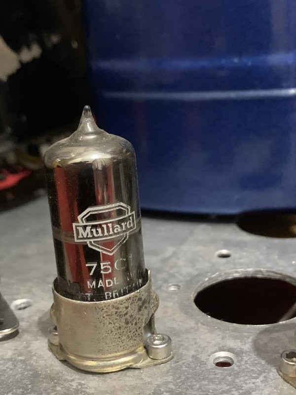
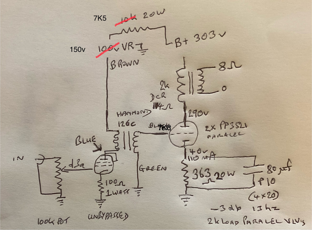
EDIT prior to the interstage primary smooth the VA from the B+ with a 75v gas reg tube set its current by ohms law from the b+ with a resistor and small choke if you have one, combined resistance using voltage drop required / .02 A the 5687 should take about .008 of the .02. Other channel to have its own VR and its own choke resistor combo. If you want to find one of the places James specified the in series capacitor for pentode screen supply, I forget and arent much bothered. I think it’ll sound good anyway. END EDIT.

Im really under too much stress looking after Diana with M.S. caused demntia, and Im half way round the bend myself. Going to Andy’s Man Club first time on Monday evening. Id like to get a more simole victory, so have diverted my attention from the gm70 amplifier as its a bigger task. And long time until positive feednack on completion, hence the simpler goal approach. Need to reach the goal.

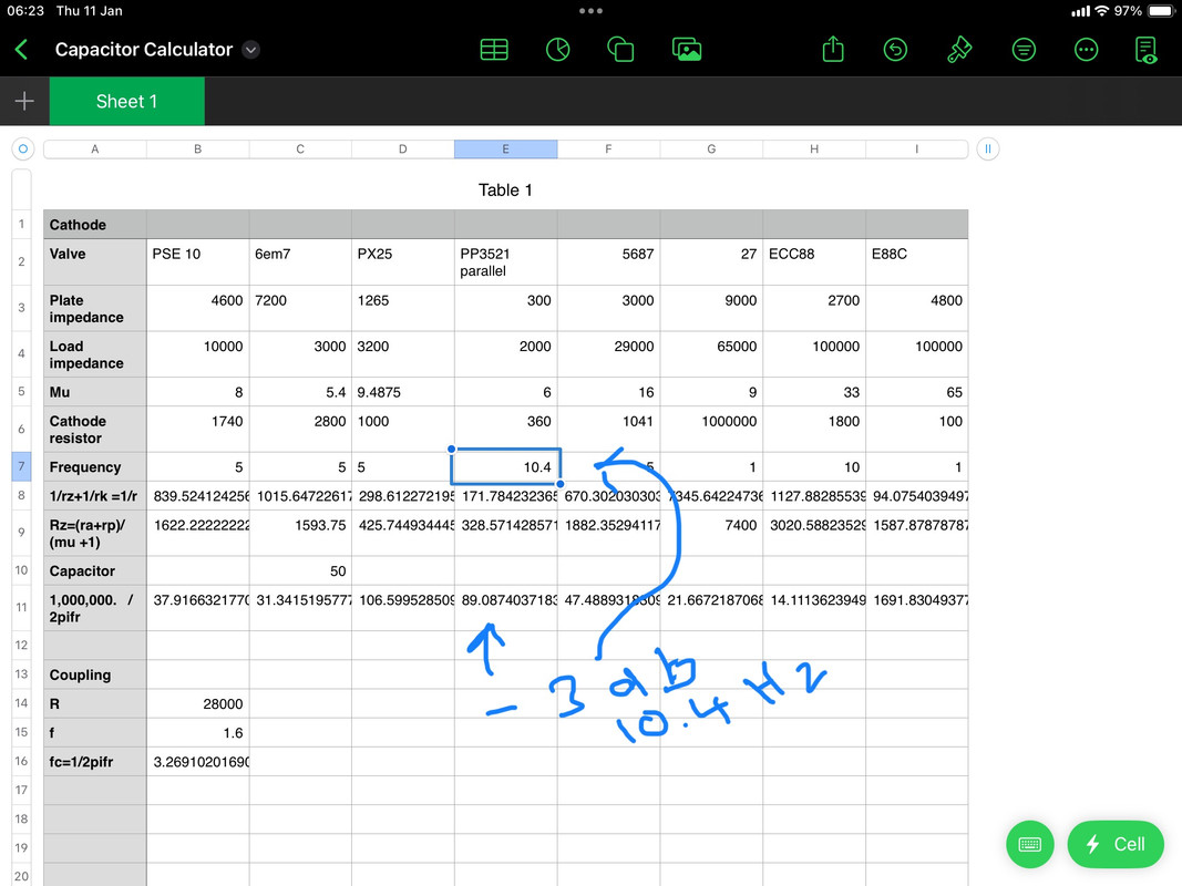
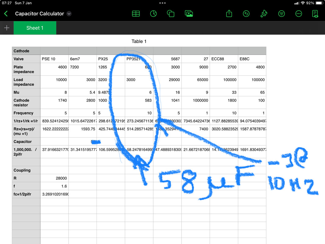
My philosophical approaches are at play in this amplifier design. Going back in time to battery bias for one, old fashioned cathode bypass on output stage, set the -3db goal not for best bass, rather for best sound of voices, which the material of the capacitor influences. Oil ideal, if I can find two of right value pio almost as good. At home I wouldnt get below 40hz anyway with my speakers and room.

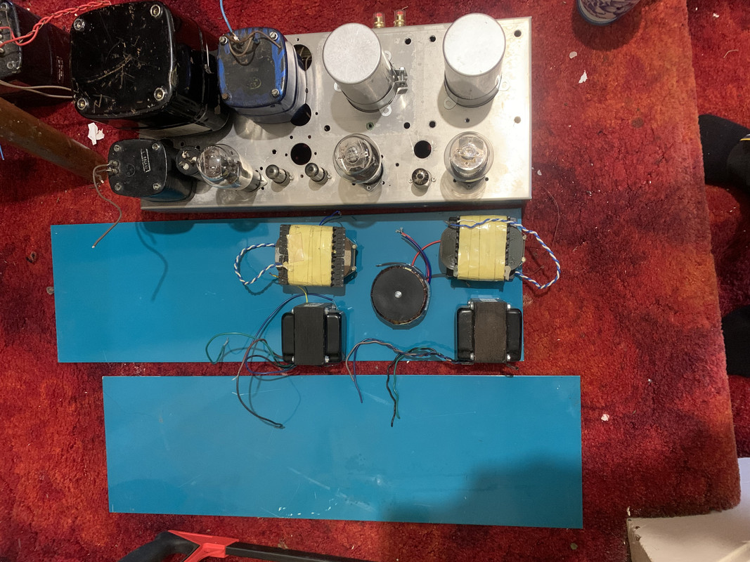
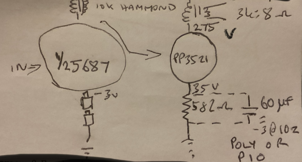
Kcant recall how to wire the hammond secondary so not pictured it in the diagram. If you build it leave connecting the secondary until you audibly test the amp. You’ll soon know which connection is right.
Diana before she drove me round the bend. Fair enough, I signed up on the bottom line to accompany her throuh life in sickness aswell as health.
Image

Image
Last edited by Paul Barker on Sun Jan 07, 2024 12:29 pm, edited 1 time in total.
"Two things are infinite, the universe and human stupidity, and I am not yet completely sure about the universe." – Albert Einstein
User avatar
Cressy Snr
Amstrad Tower of Power
Posts: 10582
Joined: Wed May 30, 2007 12:25 am
Location: South Yorks.

#92 Re: GM70 Amplifier

Post by Cressy Snr »

I’d definitely recommend AMC Paul.
I’m going tomorrow evening too. TBH I’ve missed it over the past two weeks, so it'll be nice to get back.
Sgt. Baker started talkin’ with a Bullhorn in his hand.
User avatar
Paul Barker
Social Sevices have been notified
Posts: 8998
Joined: Mon May 21, 2007 9:42 pm

#93 Re: GM70 Amplifier

Post by Paul Barker »

Thanks Steve.
"Two things are infinite, the universe and human stupidity, and I am not yet completely sure about the universe." – Albert Einstein
User avatar
Nick
Site Admin
Posts: 15759
Joined: Sun May 06, 2007 10:20 am
Location: West Yorkshire

#94 Re: GM70 Amplifier

Post by Nick »

Did you ever fix the PSE 801a amplifier? Would that not be a good place to start?
Whenever an honest man discovers that he's mistaken, he will either cease to be mistaken or he will cease to be honest.
User avatar
Paul Barker
Social Sevices have been notified
Posts: 8998
Joined: Mon May 21, 2007 9:42 pm

#95 Re: GM70 Amplifier

Post by Paul Barker »

No. Trued everything but didnt find the culprit. Not robbed anything from it though.

But the PP3521 project is well under way. I’m going to try some 2k transformers I wound years ago for 6AS7 se I never built. Tube data suggests 2k so I’ll try those they were made multilayered core transformers. Behind the scenes the 3k R cores are lurking as the backup plan.

Image

Image

Image

Image

Image

Image

Image

Image
The Hammond interstages fit side mounted inside the skirt. 35v torroid for output valves. I’ll have to unwind a torroid for rectifier. Both chokes are in series choke input 1 microfarad cap before them VA supply no more choke room resistor drop per channel to 75v VR per channel. So preamp channel seperation should be ok. Output stage ? Im kind of running out of space chokes and voltage. Ho hum.
"Two things are infinite, the universe and human stupidity, and I am not yet completely sure about the universe." – Albert Einstein
User avatar
Paul Barker
Social Sevices have been notified
Posts: 8998
Joined: Mon May 21, 2007 9:42 pm

#96 Re: GM70 Amplifier

Post by Paul Barker »

So Uncle David found two aluminium plates. So plan is cut most if top clean off and mount new top. Punch all holes in right place with no holes left over. Make a bottom out of other plate. Layout will be much same, just tidied up. Two big motor run caps mounted on top. Output transformers interstage transformers and 35v torroid mounted on base panel. The power transformer is that scope power transformer so it has two 6.3 windings one for 5687 another for 5u4 so ill resistor that down to 5v.

Decided to mount 370v 60 uF motor run caps in usual opt position for cathode bypass caps. So should all look clean lines. Ugly opts beneath.

Image

Image
"Two things are infinite, the universe and human stupidity, and I am not yet completely sure about the universe." – Albert Einstein
User avatar
Paul Barker
Social Sevices have been notified
Posts: 8998
Joined: Mon May 21, 2007 9:42 pm

#97 Re: GM70 Amplifier

Post by Paul Barker »

Image

I was in error at the 3k loadline distortion. Here is correction. Clearly our purposes are quality so 2k loadline 11% 2nd waste of time. I’ll mount the 3k transformers with which 3.16% 2nd is believable, realistic, tolerable.

Image

I have found the fault in the 801a amplifier, one output transformer is open circuit on the primary. So thats irreparable. Now I can rob it of its paper in oil cathode bypass caps. Noticing theyre much more expensive these days . So thats a bonus but the transformer is sad. At least I was right not to try fixing it. But hang on, this changes everything. Use this amp with its d3a triode VA put the 2k opt on it, buy two more vintage British Bases, make it a pse indirectly heated triode, alter the cathode resistors drop the 650v b+ with a drop on primary of transforner, variac firstly. I’ll do the maths but would expect 5 watts distortion lower than 3% as load seen by each valve is 4k.

Case already has inputs, panasonic pot and speaker connections. Few changes to VR droping resistors cathode resistors. Otherwise much faster project and as usually Nick was right.
"Two things are infinite, the universe and human stupidity, and I am not yet completely sure about the universe." – Albert Einstein
Daniel Quinn
Old Hand
Posts: 860
Joined: Thu Jan 05, 2017 9:19 am

#98 Re: GM70 Amplifier

Post by Daniel Quinn »

As somebody whose wife nursed him for two years , I know what a difficult and thankless task you are undertaking .

I also know it’s what love is . I wish you all the best , I had to say the aforementioned because I’m completely ignorant about valve amps 😉
User avatar
Paul Barker
Social Sevices have been notified
Posts: 8998
Joined: Mon May 21, 2007 9:42 pm

#99 Re: GM70 Amplifier

Post by Paul Barker »

Daniel Quinn wrote: Tue Jan 09, 2024 5:43 pm As somebody whose wife nursed him for two years , I know what a difficult and thankless task you are undertaking .

I also know it’s what love is . I wish you all the best , I had to say the aforementioned because I’m completely ignorant about valve amps 😉
Im glad you said so about my situation Daniel. Im glad this project has turned into make use of the last amplifier, just resistor values to change pretty much. Half the power but should be enoughat home anyway. I dont play heavy rock when Dianas in, and shes in. Ive ordered the second pair of valve bases.
"Two things are infinite, the universe and human stupidity, and I am not yet completely sure about the universe." – Albert Einstein
User avatar
Paul Barker
Social Sevices have been notified
Posts: 8998
Joined: Mon May 21, 2007 9:42 pm

#100 Re: GM70 Amplifier

Post by Paul Barker »

With 40uf pio cathode bypass the parallel affects the calcs to cut a long story short -3db is 25 hz. If I add another 20uF 17.5 hz yet another 20uF 13hz. Realistically I have to do that as a minimum, making 80uF capacitance per channel. So thats 4 more 20uF pio caps. So thats one issue. Next thing, what power out. Well thats 3.5 watts per parallel valve making 7 watts per channel, but the 2nd harmonic doesnt look pretty on these indirect valves, 5.5% at 7 watts.( if anyone wants to check, 2nd formula is current measurements are a,b,c,d,e. 100mA, 76mA, 55mA, 34mA, 19mA. Formula is 75*(a+e-2*c)/(a+b-d-e). But I guess we knew to expect that. After all we could determine to use px4’s instead for more linear result. But lets just build it, a 7 watt cooking amplifier. Lets face it the 6as7 se amps people have made in our group have an endearing sound, to my ears anyway, inspight of never building one myself. The 2nd on those amps might be higher. So here is my chance. It will be interesting. The valves look cute with their long plates. The full story on the broken continuity in the output transformer is, I bodged it togethr in a hurry if you recall, and who knew brown insulating tape in the hot environment of a valve amp chassis renders insulating tape not fit for purpose. It peeled itself open and the 650 volts b+ touched the earthed chassis. In less than a microsecond the thin winding wire of a transformer primary saved the rest of the power train from setting fire, acted as a fast blow fuse. But not where the contact with the chassis was made. Somewhere out of reach inside the transformer. Maybe one day I will coil wind again. But not while Im suffering demensia of a spouse which you’ll only ever understand if it happens to you, id have to invest in a new coilwinder as I sold mine years ago. Since then bought a chinese rip off of an Avo hand crank winder. But it was when the chinese machining was completely atrocious. If you want any coils wound that look like a helter skelter, Im youre man. In short it cant be made good. The moral is buy a better one that costs a lot more money. So that isnt on the horison.

Image

In my case all I have to do is change 4 jumbo valve bases for vitage BR7 pin bases. Cut out 5k transformers mount 2k transformers. Change cathode resistors on output valves to a mixture that coaps with 4 watts a d a healthy margine,, so 20 watts. Realistically mount two polyprop 83uF bypass caps, leave the 40uF pio caps in circuit. Order two 7K5 20 w resistors for the two channels vr tube current set.

Thats it. a lot quicker and easier than building from scratch. Thank you Nick for helping me see sense as per normally you have to, and yes I appreciate my friend Nick.
Last edited by Paul Barker on Wed Jan 10, 2024 2:08 pm, edited 2 times in total.
"Two things are infinite, the universe and human stupidity, and I am not yet completely sure about the universe." – Albert Einstein
User avatar
Paul Barker
Social Sevices have been notified
Posts: 8998
Joined: Mon May 21, 2007 9:42 pm

#101 Re: GM70 Amplifier

Post by Paul Barker »

The Mazda valves having a mu of 6 require much less voltage swing on the grid than the 6as7 with a mu of 2, so you cant use this circuit for the 6as7. You can use it for the 6em7 with cathode resistor alteration and redusing the b+ so the b+ is 150v to 170v for very sweet sound with great imaging, but less power than this Mazda valve which appears to turn out is closer to a px4 than the 6em7 is to a 2a3.

Now the whole indirectly heated triode situation is not at all, a poor relation to a creme de la creme battle. Indirectly heated valves have different attributes, which you cannot get from directly heated valves. Some days you will be very happy listening to youre indirectly heated triode amp, and other days you will want to play youre 45 amp through horrendously expensive highly efficient speakers that are almost impossible to get right.

You get more fun for the buck with an amp Ive portrayed here for you. Give it a go with 6em7’s.
"Two things are infinite, the universe and human stupidity, and I am not yet completely sure about the universe." – Albert Einstein
User avatar
Nick
Site Admin
Posts: 15759
Joined: Sun May 06, 2007 10:20 am
Location: West Yorkshire

#102 Re: GM70 Amplifier

Post by Nick »

Thats it. a lot quicker and easier than building from scratch.
Its easy some times to get involved with the excitement of a new "what to do" and forget to ask "why am I doing it". At least I find that all the time.
Whenever an honest man discovers that he's mistaken, he will either cease to be mistaken or he will cease to be honest.
User avatar
Paul Barker
Social Sevices have been notified
Posts: 8998
Joined: Mon May 21, 2007 9:42 pm

#103 Re: GM70 Amplifier

Post by Paul Barker »

Its a time waiting for parts to arrive. I didnt like the thought of adding a polypropylene cap for the sake of bass response. Realised my four pio’s are 30 uF each, Ive ordered two more so now my bypass value is 90uF all same material. I’ll suffer -3db at 10 hz. Ive never had a speaker that goes as low as 30 hz anyway or a room acoustic for it either. So here is the maths.

Imagepic share

Oh and I realised 360 ohm 20 watt caps are available so ordered those. Also realised 20 watt 7k5 not available. So altered the dropper resistor value to 6k8, no big deal 22ma instead of 20.
"Two things are infinite, the universe and human stupidity, and I am not yet completely sure about the universe." – Albert Einstein
User avatar
Paul Barker
Social Sevices have been notified
Posts: 8998
Joined: Mon May 21, 2007 9:42 pm

#104 Re: GM70 Amplifier

Post by Paul Barker »

I was checking my maths on the d3a version and discovered I’d made an error from the beginning, it wouldn’d have suited the Hammond interstage, too much internal resistance. Tried to make the 5687 work, but too low mu. So checked the suitability of ECC88/E88CC Which just makes the minimum requirements of no more than 15 mA dc current through the Hammond 126C interstage, yet enough input sensitivity to drive the grids of PP3521 pair to full power output, which requires 1.3v rms from the source. The sound of other valves I’d prefer, but the other elements of the design to benefit sound quality to my ears with my experience are all met. 1/ The VA cathode resistor is unbypassed, which to my ear is the best sounding option when the choices are capacitor bypassed auto bias, battery biased, un-bypassed resistor auto biased. There is no coupling cap. The output stage is autobias bypassed with paper in oil. My preferred capacitor type in this position.

So the maths has chosen the valve and the preferences have accomodated the choice of valve. I expect the result good. Any other choice for this topology would compromise power out / sensitivity and frequency response through the interstage transformer, which is the elephant in the room I accidentally ignored.

Image

Just going off memory the power out is 7.5 watts at 5% second harmonic distortion. When the parts arrive and its built I’ll review to sound. Ill mirror this post to the dormant PP3521 thread also. The gm70 thread can stay alive as that amp is suspended not ceased.
"Two things are infinite, the universe and human stupidity, and I am not yet completely sure about the universe." – Albert Einstein
Post Reply