RH2A3

If they glow, this is the place to be
User avatar
Paul Barker
Social Sevices have been notified
Posts: 8985
Joined: Mon May 21, 2007 9:42 pm

#256

Post by Paul Barker »

Alex Kitic wrote: How much capacity were you adding, and where were you connecting it?
After the bridge 200µF

Alex Kitic wrote: This might be also a good direction, but again it would mean tampering with the units, and it is not something DIYers might easily replicate.

I actually haven't got a scope, nor any means of measuring this high frequency AC (my DMM is good up to 400Hz). While this makes me a little bit nervous (sensitive TT filaments), tests with DC heating (9V, 9.5V, 9.8V tried) have confirmed to me that based on the heaters light intensity I am hitting the correct voltage, probably 9.8 or 9.9V. I am using one 0.15 ohm resistor on each leg, meaning that at 5A current draw, the total voltage drop is 1.5V; the electronic transformer unit is specified as 11.2V-11.7V (depending on current, obviously), so assuming 11.5V at 5A current draw, the filaments get 10V... probably 9.9 or 9.8, but not more than 10V.

The good thing here is that output voltage is supposed to be current draw sensitive, but rather insensitive of mains fluctuation.


Particularly because you have compared it to standard mthods I am happier that you are aware of the pitfalls and have the filament voltage pretty correct. This was always an anxiety for us.
"Two things are infinite, the universe and human stupidity, and I am not yet completely sure about the universe." – Albert Einstein
Alex Kitic
Old Hand
Posts: 369
Joined: Mon Oct 14, 2013 3:20 pm

#257

Post by Alex Kitic »

Nick wrote: Thats fine, we have different opinions about what done properly means, thats not a problem. My point is that we have tried DC a lot and there is more to it than just getting the noise low (though thats a start).

Well, with DC, its possible in my experience to get noise 20dB below what can be heard, and its only at that sort of level it stops doing harm. And no it doesn't imply that, it may be you have some source of buzz (can't say what buzz means without seeing or hearing it, but I assume you mean something with high frequency components) that is covered up when using AC heating by the 50Hz component.
I assume that by "below audible" you mean "not audible in normal use, at the listening position"... or is it virtually inaudible (with your ear on the speaker)?
If the first option is correct, than I agree with you completely on noise levels. In that case I am getting this result even with an LM1084, and even better on AC (mains 50Hz) with lower voltage DH tubes.

As for the buzz, I might make a recording with a phone, placed at a few cm from the speaker. Anyway, this is mostly higher frequency repetitive noise (medium frequency, rather than a high frequency hiss). And yes, it is not masked below Ac hum, since it is more prominent in the audibility context than hum is (why I insist on being more sensitive to buzz than hum).
Alex Kitic
Old Hand
Posts: 369
Joined: Mon Oct 14, 2013 3:20 pm

#258

Post by Alex Kitic »

Paul Barker wrote:
Alex Kitic wrote: How much capacity were you adding, and where were you connecting it?
After the bridge 200µF

Particularly because you have compared it to standard mthods I am happier that you are aware of the pitfalls and have the filament voltage pretty correct. This was always an anxiety for us.
Besides the possibility to blow the electronic transformer by adding capacity, I am even more concerned with the possibility that this might raise the voltage on the heaters.

I will look again into the cancellation schematics to see how to adapt the cathode resistor version to electronic transformer heating... wouldn't it be more logical to inject part of the noise directly (across a cap)?
User avatar
Nick
Site Admin
Posts: 15748
Joined: Sun May 06, 2007 10:20 am
Location: West Yorkshire

#259

Post by Nick »

I assume that by "below audible" you mean "not audible in normal use, at the listening position"... or is it virtually inaudible (with your ear on the speaker)?
Sort of, what I actually mean is that once you get noise down that far, you find that the overall sound improves, its not the bits you can hear as a signal that does the damage (though if you can hear it its too high), its the effect that noise has on the audio signal that happens with noise far less than you would expect or hear directly.
Whenever an honest man discovers that he's mistaken, he will either cease to be mistaken or he will cease to be honest.
User avatar
Paul Barker
Social Sevices have been notified
Posts: 8985
Joined: Mon May 21, 2007 9:42 pm

#260

Post by Paul Barker »

Alex Kitic wrote: Besides the possibility to blow the electronic transformer by adding capacity, I am even more concerned with the possibility that this might raise the voltage on the heaters.
No fear of either. Quite a few of us have walked this way before.
those two fears are unfounded.
Alex Kitic wrote:I will look again into the cancellation schematics to see how to adapt the cathode resistor version to electronic transformer heating... wouldn't it be more logical to inject part of the noise directly (across a cap)?
You'd have to ask Stephie Bench any questions, but I don't know if Stephie is accessible these days.

I wouldn't try to alter anything of Stephie's. I am too dumb. If you think you are cleverer be my guest.
"Two things are infinite, the universe and human stupidity, and I am not yet completely sure about the universe." – Albert Einstein
Alex Kitic
Old Hand
Posts: 369
Joined: Mon Oct 14, 2013 3:20 pm

#261 VICTORY!

Post by Alex Kitic »

Paul Barker wrote:
Alex Kitic wrote: Besides the possibility to blow the electronic transformer by adding capacity, I am even more concerned with the possibility that this might raise the voltage on the heaters.
No fear of either. Quite a few of us have walked this way before.
those two fears are unfounded.
What else can I say, but Victory!
I opened the boxes and analyzed the circuitry, found the bridge (1N4007) diodes, checked the polarity... and found as well the 156nF/400V cap inside! The wires are basically paralleling the outside capacitor (330uF/400V) with the small cap inside.

I did it first with one... to be able to compare the channels. I was literally floored when there was absolutely nothing on the tweaked channel! While the normal channel had some hum/buzz (not much, but quite audible near the speaker) the tweaked channel has nothing... well, maybe we could trace something on the scope, but all that can be heard is some tube noise from the tweeter (with one ear stuck in the tweeter). I had to call my daughter to verify whether there is something else to be heard that I do not hear... but she does not hear it either.

Procedure repeated with the other unit, boxes closed - just two wires sticking out, connected to the caps. Total silence at power-up, incredible... I had to play some music to be sure it is working.

Thus, VICTORY - no hum, no noise... combined with AC simplicity and, what is most important in my opinion, the fact that the whole filament is at the same potential (which is the main issue with DC heating, regardless of type - current regulated, voltage regulated, battery operated...).

Now for the "bad news".
I had the impression that the tweaked channel tube was slightly brighter lit (it is difficult to tell exactly, since the two tubes are, unfortunately, not physically identical, one is an RCA the other a Haltron). Besides, it started faster than the normal channel. It is thus my impression that the tweak actually affects the output voltage...

Since I cannot measure high frequency AC voltage, I did some informative measurements for comparison sake. The normal channel shows (both did without the tweak) a reading of 28-29V AC, while the tweaked channel shows 43V. The drop across a 0.15 ohm resistor is almost identical on all 4 resistors, at 0.87V. It is my impression that the voltage has risen at least 0.5-0.7V AC after the tweak.

To feel safer, I quickly found some resistors and added 0.11 ohms on each channel. The drop across this resistor has a reading slightly lower than the 0.15 ohm resistors... and the resulting voltage is shown as 31V. From that I deduct that after adding the 0.11 resistor the heater voltage is again "normal". At 5A current draw, the additional resistor should be dropping some 0.55V... and judging by the light of the tubes, I have the impression that it is correct (like before).

The voltage increase could probably be calculated, and I believe it is caused by the decrease in ripple (effectively, decreasing ripple means elevating the RMS DC voltage). If the resulting AC increase is a percentage related to the increase in DC voltage, that's easy to counter with additional resistors. Besides calculating, it is quite easy to measure the DC voltage at the cap wires with and without the cap...

But there must be a means to measure high frequency AC voltage, without spending 1000 USD for a voltmeter?!

Paul Barker wrote:
Alex Kitic wrote:I will look again into the cancellation schematics to see how to adapt the cathode resistor version to electronic transformer heating... wouldn't it be more logical to inject part of the noise directly (across a cap)?
You'd have to ask Stephie Bench any questions, but I don't know if Stephie is accessible these days.

I wouldn't try to alter anything of Stephie's. I am too dumb. If you think you are cleverer be my guest.
I checked the explanation Steve gave (I admit never reading it before) and understood - this is not plain AC injection, but rather the injection of the fundamental and subsequent harmonics, filtered in a precise way.

I would not modify anything there... but it does not seem to be applicable to the HF AC heating method. Most importantly, there is absolutely no need to get that far, since adding a cap does the trick.

What puzzles me now is - have you had such extremely good results with HF AC (no hum, no buzz, nothing!) in your experiments? Maybe the tweak decreases hum/buzz/noise to a point where it becomes inaudible with the RH circuitry (as commented before, hum from direct heated tubes on normal AC mains is a lot lower than with a no-feedback circuitry, from almost inaudible to negligible)...
Attachments
IMG_2399_filtered_web.jpg
User avatar
Paul Barker
Social Sevices have been notified
Posts: 8985
Joined: Mon May 21, 2007 9:42 pm

#262 Re: VICTORY!

Post by Paul Barker »

Alex Kitic wrote:
What puzzles me now is - have you had such extremely good results with HF AC (no hum, no buzz, nothing!) in your experiments? Maybe the tweak decreases hum/buzz/noise to a point where it becomes inaudible with the RH circuitry (as commented before, hum from direct heated tubes on normal AC mains is a lot lower than with a no-feedback circuitry, from almost inaudible to negligible)...
YES The 212 amp I used to take to Owsten.

I too was always anxious about the voltage though.
"Two things are infinite, the universe and human stupidity, and I am not yet completely sure about the universe." – Albert Einstein
Alex Kitic
Old Hand
Posts: 369
Joined: Mon Oct 14, 2013 3:20 pm

#263

Post by Alex Kitic »

Nick wrote:
I assume that by "below audible" you mean "not audible in normal use, at the listening position"... or is it virtually inaudible (with your ear on the speaker)?
Sort of, what I actually mean is that once you get noise down that far, you find that the overall sound improves, its not the bits you can hear as a signal that does the damage (though if you can hear it its too high), its the effect that noise has on the audio signal that happens with noise far less than you would expect or hear directly.
You are correct about that - noise does interfere with the sound, even when it is not particularly audible. I learned that practical lesson a long time ago with my first phono preamps. In part, believing that the sound should further improve with a decrease in spurious components - is what drives me to try various heater arrangement solutions.

But now that the HF AC works so perfectly, I guess I found my "perfect solution". And the sound has improved, of course... the details, the fluidity.

What remains to be solved is a way to measure the HF AC...
Alex Kitic
Old Hand
Posts: 369
Joined: Mon Oct 14, 2013 3:20 pm

#264 HF AC VOLTAGE MEASUREMENT

Post by Alex Kitic »

I needed to find a way to make some meaningful measurements, because I guess that this great (and cheap?) method to heat DHTs and DHPs, particularly those with high current and/or voltage requirements - has little meaning without a proper way to check the heater voltage applied.

Yesterday I was under the impression that even after the additional 0.55V (0.11 ohm with 5A) drop the voltage has remained rather high. My reading of 31V should have some meaning?

The only accurate way to measure HF AC is heat/power into a resistor. Well, the filament of a 813 is effectively a 2 ohm load once heated. Starting with my previous measurements, approximately 29V should be the correct voltage. Trying to make some sense out of it, 28.28/2.828=10V. Thus 31/2.828=10.96V Assuming that the DMM measures peak (peak to peak) voltage across a thermal load, voltage is too high, and I need to do something about it.

Another way to measure is adding a diode and a cap in parallel with the heater of the tube and get the DC measurement: it should be ACx1.41 -- of course, the diode must be a Schottky, and the ultra-low voltage drop actually helps get the voltage really near ACx1.41. Well, with a "concoction" made out of a diode and a cap and some wires, I had a 15.35V DC reading, which equates to 10.87V. Excellent (not for the heater of the poor 813 under torture, but for the scientific method...)!

Starting from the two 0.15 ohm resistors already installed, I added 0.33 (3x 1 ohm in parallel) in series, instead of the 0.11 that was tried yesterday. This should give a total voltage drop of 3.15V at 5A draw. As a matter of fact, I measured 13.84V DC on one tube (9.8V AC) and 13.9V DC on the other (9.9V AC)... and was happy with the result. I am also happy with the brightness of the tube.

In addition, the AC reading across the heater is between 28 and 29V (after a while of operation and heating), which all goes toward a very good approximation of the necessary 10V needed.

While the AC readings might not necessarily make much sense (including my silly p-p approximation)... after all, my DMM is not even TrueRMS... the DC reading should be spot-on. Starting from there, it should be rather easy to adapt the system to a variety of tubes. For instance, the 2E22 would definitely benefit from this level of hum and noise.

Last but not least, the noise/hum/buzz. This time listened to without preamplifier... in all sincerity, with windows closed, and home alone in almost total silence, with my ear on the midrange or tweeter, I can detect a very very faint, virtually inaudible buzzz (the solid-state buzz I was mentioning previously). As the preamp is powered on, it literally floods with noise (shhhhhh) and drains this very very faint buzz that becomes inaudible. Tube noise is something we cannot completely avoid (in this case, it is 5670 in the line stage of my RPA... I am using them for some 10 years already, they measure fine but maybe noise levels have increased... nevertheless, it is not something worth doing anything about, one actually never notices it because we do not stick our ears in midranges and tweeters - rather, we sit in an (arm)chair and listen to music.

Does anyone have the impression that my math here is not correct or that I have missed something important? I am trying to establish a method to make a reasonably accurate reading of the HF AC for the heaters - because in the end these "electronic transformers" vary a lot and the DIYers should actually get what he can, paying attention only to important stuff - safety, minimum load, the presence of various protections on the unit (short-circuit protection, no-load protection). Once the units are there, we just need to have a way to establish whether the voltage supplied to the heaters is correct (as it will be different than specified once the cap is added).

This also leads me to think about how to adapt the output voltage manipulating the DC on the "input" to the circuitry, i.e. "behind the bridge" as Paul has put it. Maybe we can decrease the output voltage by decresing the DC... just like an increase in voltage due to the ripple smoothing action of the cap has increased the output voltage... even regulating it should be fairly easy, but is probably unnecessary... ?
User avatar
Nick
Site Admin
Posts: 15748
Joined: Sun May 06, 2007 10:20 am
Location: West Yorkshire

#265

Post by Nick »

it should be ACx1.41
Thats only true if the wave in question is a sine wave. Thats the problem, the one we had (at least) wasn't, it was a distorted square, hence the problem finding the actual RMS voltage.
Whenever an honest man discovers that he's mistaken, he will either cease to be mistaken or he will cease to be honest.
User avatar
Paul Barker
Social Sevices have been notified
Posts: 8985
Joined: Mon May 21, 2007 9:42 pm

#266 Re: HF AC VOLTAGE MEASUREMENT

Post by Paul Barker »

Alex Kitic wrote: Another way to measure is adding a diode and a cap in parallel with the heater of the tube and get the DC measurement: it should be ACx1.41 -- of course, the diode must be a Schottky, and the ultra-low voltage drop actually helps get the voltage really near ACx1.41. Well, with a "concoction" made out of a diode and a cap and some wires, I had a 15.35V DC reading, which equates to 10.87V. Excellent (not for the heater of the poor 813 under torture, but for the scientific method...)!
I think you are over optimistic.

you must have a very large cap and a very low forward voltage drop diode and also don't forget you are using a formula which works only with a pure signwave.

But you are on the right lines.

If I were you I would check your results with a perfect signwave 10v ac filament supply and look for same brightness and also same dissipation. so your method ends up giving you no advantage except to provide you with a working formula to then apply to all future projects. Do you understand me? but your formula will not be based on 1.414 factor for the bastard waveform. The formula will factor in your diode drop too. I think you may end up at 1.3 something. IF you do, this means that your ac is higher than you think it is.
"Two things are infinite, the universe and human stupidity, and I am not yet completely sure about the universe." – Albert Einstein
User avatar
Paul Barker
Social Sevices have been notified
Posts: 8985
Joined: Mon May 21, 2007 9:42 pm

#267

Post by Paul Barker »

Nick and I posted simultaneous. Great minds. :)
"Two things are infinite, the universe and human stupidity, and I am not yet completely sure about the universe." – Albert Einstein
Alex Kitic
Old Hand
Posts: 369
Joined: Mon Oct 14, 2013 3:20 pm

#268

Post by Alex Kitic »

OK, these are comments I was prepared for - actually I tought about that myself.

The diode is among the lowest forward voltage available, approximately. 0.220V (my DMM indiode mode actually shows the forward voltage of the diode under test).

The cap is 2x4700uF in parallel (rather large for measurements purpose, I think). And there is virtually no load of any relevance aside the DMM.

I have yet to check it against a 50Hz source for reference. That I will do tomorrow.

As for the output of the electronic transformer, it should be 40kHz, but "in 50Hz format". A 50Hz wave-form "filled" with rapid bursts, if I am explaining myself correctly. Once rectified, it gives the same result as if the source was 50Hz, i.e. ripple is 50Hz fundamental for half wave, or 100Hz for full wave rectification. At least, that is the theory, and I have no way to check it directly.

Assuming 1.41x 10V= 14.1 less 0.220V drop = 13.88V. Thus 13.84/1.388=9.997V and 13.9/1.388=10.01V Spot-on, actually?

In my view, since we are trying to measure DC (easy) and calculate AC from there (tricky but feasible), the true nature of the AC waveform is not that important, since we are converting it to measurable DC. The need to check against a messurable AC source is a fact, but it should not deviate too much from the proposed coefficient (with a diode of the same type and a cap the same size). I will check tomorrow.

The difference between 1.388 and 1.41 is less than 16%, while my DMM is certified as 5% precision. I could be measuring 10V for anything between 9.95 and 10.05V without knowing which is correct. With mains fluctuations (strangely, at my home just between 222V and 227V, it never gets to 230 nor 220, but I read that even in Germany it varies more than that), I guess wishing for more precision would be hair-splitting (literary translation).

As for heaters brightness, I am quite confident with this level, just like I was not with the increased voltage even without a means to measure.

BTW, any ideas about the AC reading across the hot 2 ohm load (the heater)? The DMM measures average AC... thus it should detect the peak to peak value of the drop across the thermal resistance with 5% precision (28.28 could be read as 29.69 or 26.86, and my readings today were between 27.8 and 29V - which ultimately coincides with approximately 10V).
User avatar
Nick
Site Admin
Posts: 15748
Joined: Sun May 06, 2007 10:20 am
Location: West Yorkshire

#269

Post by Nick »

In my view, since we are trying to measure DC (easy) and calculate AC from there (tricky but feasible), the true nature of the AC waveform is not that important, since we are converting it to measurable DC. The need to check against a messurable AC source is a fact, but it should not deviate too much from the proposed coefficient (with a diode of the same type and a cap the same size). I will check tomorrow.
Sorry, no, you are trying to measure the RMS voltage because you need to know what the equivalent heating effect is. The nature of the AC waveform is vital. All you are doing is measuring the peak level. Upi need to know the crest factor of the wave to calculate the RMS value. And to know that you need to see what shape it is.
Whenever an honest man discovers that he's mistaken, he will either cease to be mistaken or he will cease to be honest.
User avatar
Paul Barker
Social Sevices have been notified
Posts: 8985
Joined: Mon May 21, 2007 9:42 pm

#270

Post by Paul Barker »

This might help.

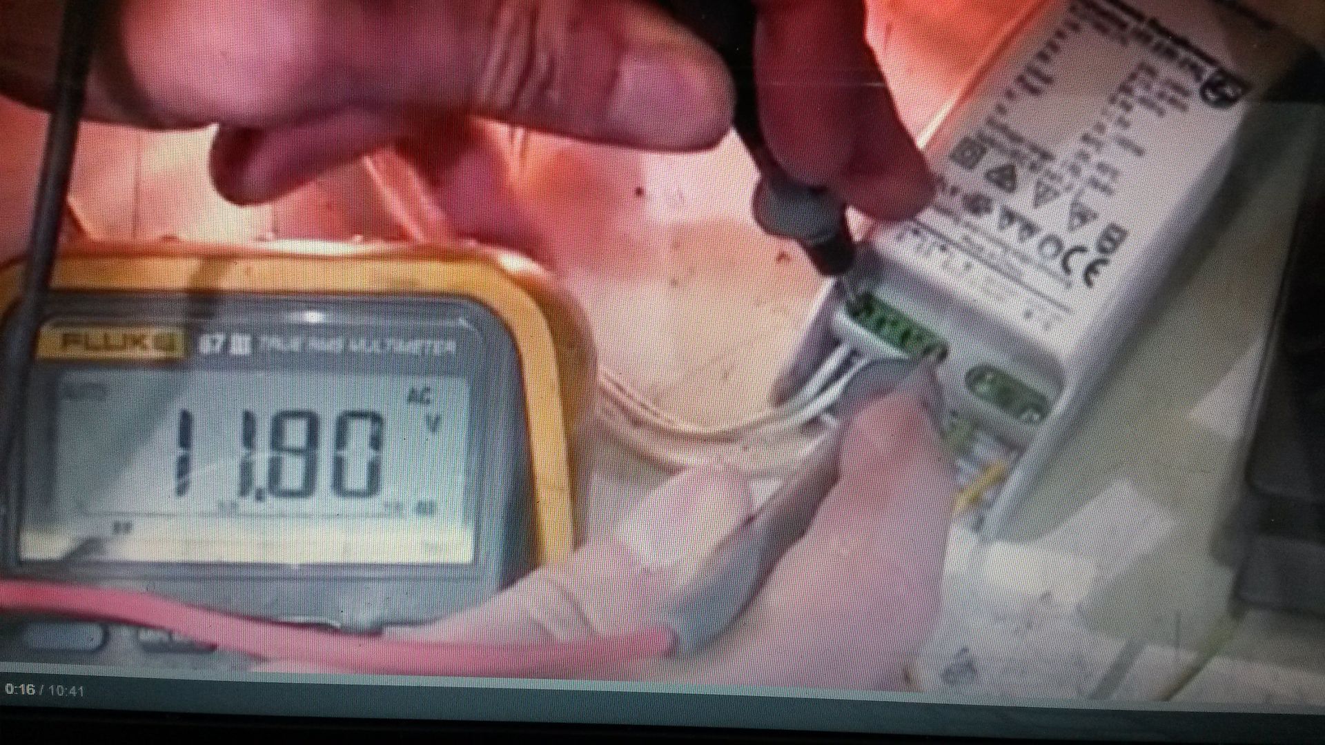
There is a fairly reliable fact, that the manufacturer of the transformer has to meet standards. So in original form it produces a little under 12v.

googling the problem I found a very informative guy who shows his true rms voltage reading at 11.8v so that makes perfect sense.

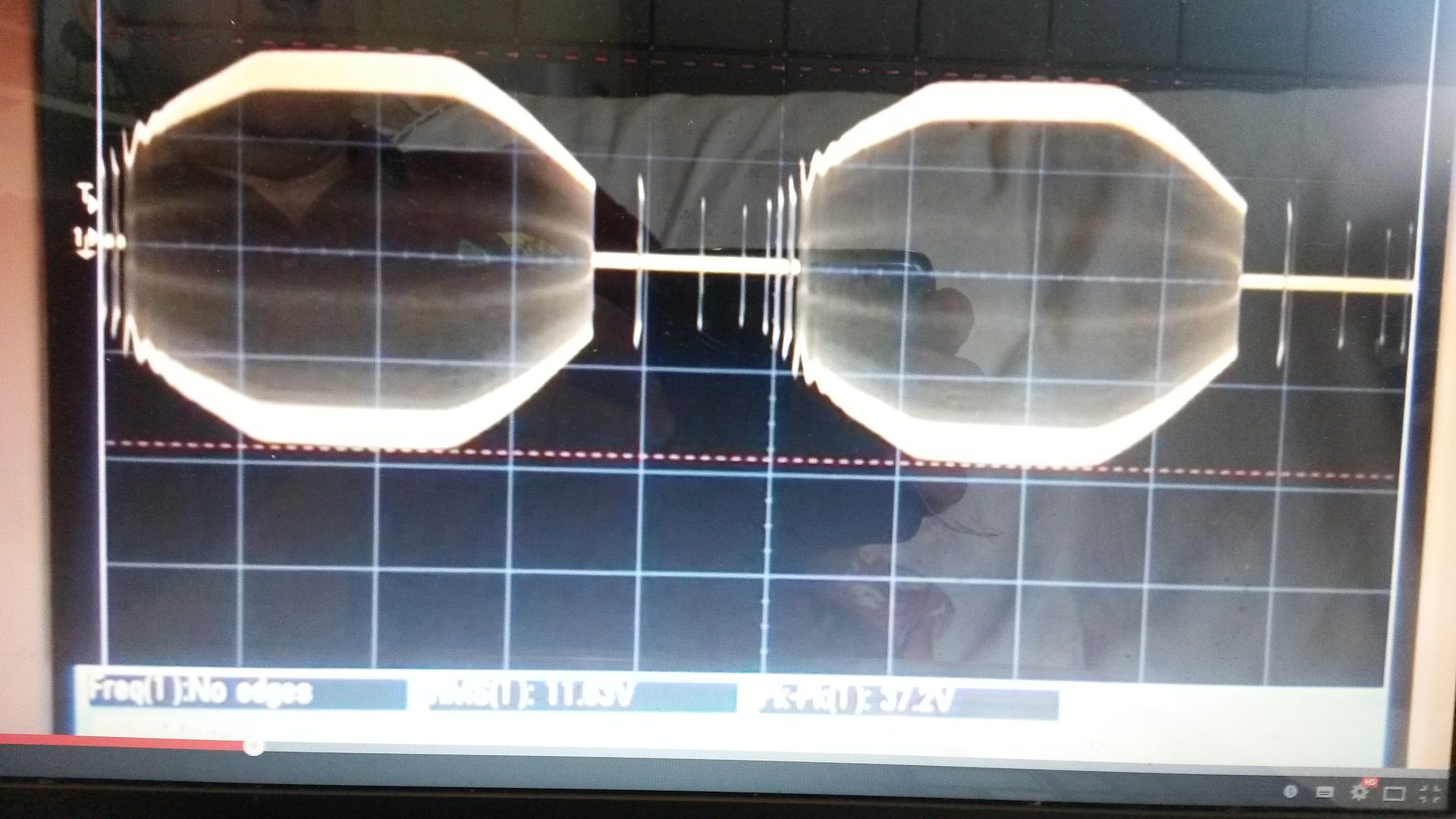
Image

A couple of other pointers. He shows the 100hz pulses (because he hasn't added the cap after the first bridge as the 100hz pulses don't matter in his world.

Image

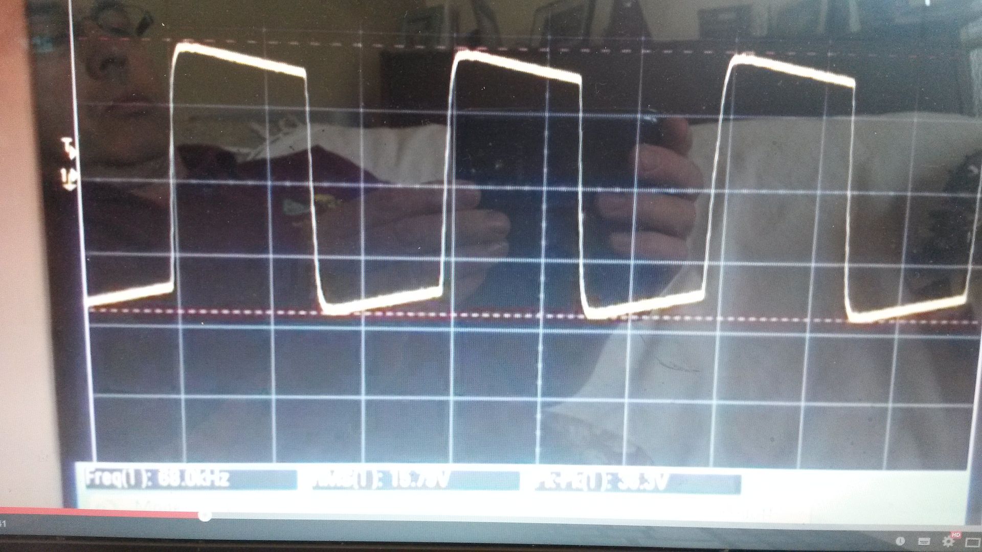
He shows his own scope measurements which give us an indicator of frequency with the modern units,
Image
which clearly differes from what we experienced back in 2003 / 2004 when we were experimenting with this. We found the frequency of operation 24khz and I remember easily getting it up to 50khz by unwinding some turns off the rf choke. I think Triode Kingdom (the originator of the use of lighting transformer, but not the originator of the idea of RF AC heating of filaments: which was a man called Par back on the Jo List circa 2002) <the Jo list was an email group which formed after the demise of Sound Practices, I was on it but the email address I used at that time is long defunct so my mains from it are somewhere out in the ether> anyway King managed to get it up to 64khz or thereabouts.

Anyway this doesn't seem to matter now, as the youtube I found shows that in todays form these transformers run at 60khz or so, but it apparently varies.

The relationship between Pk to PK and RMS appears to be 3.19 from the screen shots of his scope traces, the overall waveform is a square wave with sloap but not bad rise time. It isn't that uggly I recall in our day it looked much worse.

He also showed the RF suppression on the input. This is fundamental in hifi to make sure you don't put back into the same line you are using for your sources phone stage preamp ect RF noise from this SMPS. I would suggest that the standards of the domestic power industry which these electronic lighting transformers have to adhere to are not adequate for good hih sound.

So you definately need to supplement the RF supression. Without a scope, one approach would be to assume they have correctly designed it for the frequency of operation, and duplicate it. So you could buy two of these cheap transformers to use one, and rob the rf suppression components from the spare to put in series with the existing one.

I think it has been made easier today by the frequency they are now using. I believe the main problem you will encounter is RF noise affecting everything else plugged into the same main power source unless you supplement the RF filtering.

"Two things are infinite, the universe and human stupidity, and I am not yet completely sure about the universe." – Albert Einstein
Post Reply