SRPP Series Shunt Reg Anyone?

If they glow, this is the place to be
User avatar
Cressy Snr
Amstrad Tower of Power
Posts: 10582
Joined: Wed May 30, 2007 12:25 am
Location: South Yorks.

#1 SRPP Series Shunt Reg Anyone?

Post by Cressy Snr »

As you all know I've been thinking about regulators (sad I know)

Paul's suggestion of a series regulator followed by a shunt reg, Nicks push pull regulator musings and a bit of Morgan Jones appears to have led me to
the realisation that the SRPP circuit if configured as a regulator is if you look at it exactly that;
a series followed by shunt reg.

So I have tried to design one around a 6080 double triode as below.

Image

I have elevated the cathode of the shunt valve so that it sits at approximately half the raw HT, so that I can (very roughly) split the drops across each valve to about 100V each.

100V drop at 40mA through the series valve gives a bias of around 42V which is provided by the voltage drop across the 1K resistor being fed back to the grid of series valve.

The shunt valve bias is provided by the potential divider across the output of the whole thing.

A problem I can see is the low gain of the 6080. In this arrangement, the shunt valve has two duties to perform, as it not only has to regulate but also
provide the error-amp function for the series valve and with its crappy gain of only 2, maybe it is not going to be that good.

So I read a bit of a Hunt and Hickman paper I found on the interweb where they used a constant current approach to improving the DC regulation for the scientific instruments.

Looking at that and bringing it up to date, I simply stuck a current regulating diode at the bottom of the potential divider network on the output.

This is only a start so any comments would be gratefully received.
I'm already thinking about maybe using a pair of triode strapped 12GN7s
to replace the 6080.

They have a Pd of 10W and high gain/gm which might allow the shunt valve to better perform as an error amplifier.
User avatar
Paul Barker
Social Sevices have been notified
Posts: 8988
Joined: Mon May 21, 2007 9:42 pm

#2

Post by Paul Barker »

The 5k6 resistor you got the idea from the plate load of the error amplifier in a conventional series pass design. It is without purpose here. Unless you are using it to strike the VR tubes. This is not necessary. The 6080 when it heats up will pull sufficient current to strike the VR's and plenty to maintain them. If you prefer the vR's to be up and running before the 6080 heats up then a 10mA current set resistor would be plenty. So that would be 22k.

I can't get my head around the 2ma constant current on the voltage sensing section. I am not sure it will make the slightest bit of difference except contibute the sound of solid state. You may aswell use zenners on the cathode of the totem pole if you are happy with solid state.

rightly you have recognised the VR tubes will contribute a little noise. The 100nf is the maximum you are allowed without a resistor in series for the 75C1, but I don't know about the vintage British VR tubes they may be more upset by capacitance. So you would be researching the zobel arrangements I am sure you are familiar with from your pentode experiences.

I don't think the mu of the bottom 6080 is a major handicap if you consider it's effectiveness is more in the current by which it pulls down the power supply. See it as a shunt regulator and the massive transconductance is your benefit. So with this tube choice you are erring on the side of shunt regulation. Change the line up for higher mu and you will err towards series regulation. Take your choice.
User avatar
Paul Barker
Social Sevices have been notified
Posts: 8988
Joined: Mon May 21, 2007 9:42 pm

#3

Post by Paul Barker »

By the way the last cap shouldn't be necessary if you shunt as much current as your amp demands.

I did manage to breadboard a power supply capable of providing for an output stage of 260v 50mA using two of the venerable old British 4 pin regulators pulling about 50mA. I just chopped and changed the ones I have to get the required effect.

It was a pleasing sound there was no need for an LC stage after the Vr tubes.

Then I went back to my old fathful method. because it was such a low voltage Iw as working with the 572b my favourite chunt valve just wouldn't play ball. With a little manual intervention to strike the VR's the 830b does the job beautifully. I only breadboarded a little single channel Darling amp drawing 50mA in total and shunted 100mA with the 830b so that it could also provide for the second channel. The power transformer is 300v 500mA.
User avatar
Cressy Snr
Amstrad Tower of Power
Posts: 10582
Joined: Wed May 30, 2007 12:25 am
Location: South Yorks.

#4

Post by Cressy Snr »

Paul Barker wrote:The 5k6 resistor you got the idea from the plate load of the error amplifier in a conventional series pass design. It is without purpose here. Unless you are using it to strike the VR tubes. This is not necessary.
Yes I was using it to strike the VR tubes but I'll bow to your greater experience and take it out. I wondered whether it would be necessary in the first place but stuck it in just in case. Its one more component I don't have to use. :)

Re the ccd under the potential divider...not sure now :?

Here's their paper anyway.

www.tubezone.net/pdf/diagrams/regulator.pdf

Thanks for the endorsement and the reassurance about the bottom 6080.
It's a completely new area for me so its nice to at least be on the right lines.
User avatar
Paul Barker
Social Sevices have been notified
Posts: 8988
Joined: Mon May 21, 2007 9:42 pm

#5

Post by Paul Barker »

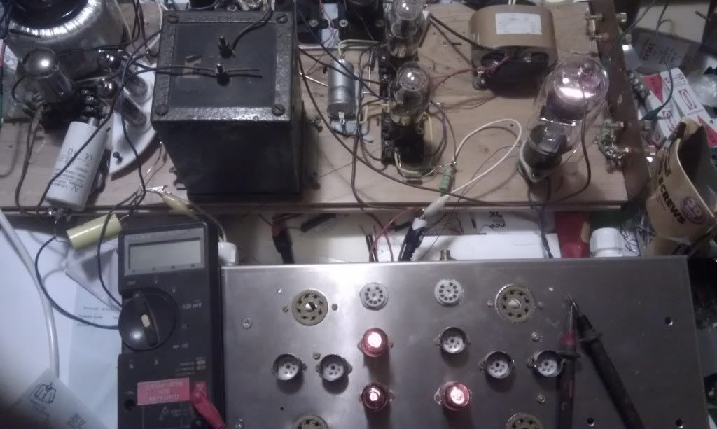
In the still pic, the three 75v VR tubes are in the little chassis in forground the 830b on the wooden breadboard.

In the first video this version which has 100mA shunted by the 830b is playing.

In the second video the two british VR tubes are doing all the shunt work.

In both cases the mechanism by which the shunt current is determined is varying the resistance of the power supply. The node where HT is taken from is after the series current set resistance because we need to keep the impedance of the B+ to ground route for the shunt element which completes the AC signal loop.

The sound is pure from both methods. The 1626 sounds sweet and delicate, but is low powered. I would probably need 98db speakers to make use of it. It was only a fun breadboard to experiment with regulators.

Image

OK I have to work out how to embed photobucket video.
User avatar
Cressy Snr
Amstrad Tower of Power
Posts: 10582
Joined: Wed May 30, 2007 12:25 am
Location: South Yorks.

#6

Post by Cressy Snr »

Thanks for the pics Paul

here is the simplified cct

Image
User avatar
Paul Barker
Social Sevices have been notified
Posts: 8988
Joined: Mon May 21, 2007 9:42 pm

#7

Post by Paul Barker »


User avatar
Paul Barker
Social Sevices have been notified
Posts: 8988
Joined: Mon May 21, 2007 9:42 pm

#8

Post by Paul Barker »

SteveTheShadow wrote:Thanks for the pics Paul

here is the simplified cct

Image
I would breadboard it like that and see if the VR's strike gracefully. But they may require assistance of a 10mA resistor where you placed yours.

I am just not sure what the CCS would do for you on the voltage sensing section which is of benefit. KISS. It does add a potential fuse.
User avatar
Paul Barker
Social Sevices have been notified
Posts: 8988
Joined: Mon May 21, 2007 9:42 pm

#9

Post by Paul Barker »

SteveTheShadow wrote:Yes I was using it to strike the VR tubes but I'll bow to your greater experience and take it out. I wondered whether it would be necessary in the first place but stuck it in just in case. Its one more component I don't have to use. :)
I might be wrong so I would put a strike resistor in but it just needs to provide 10mA in your scenario you are using up valuable current handling capacity of the VR's best kept to place them in the middle of their operating range rather than at the top. Though my second video shows the SR130 is happy at 100mA it puts on a light show which it may not be able to sustain. I am not sure what all the gas lapping up the side of the metal structure means. maybe that one is soft, the other one doesn't do it.

There is no noise.
User avatar
Cressy Snr
Amstrad Tower of Power
Posts: 10582
Joined: Wed May 30, 2007 12:25 am
Location: South Yorks.

#10

Post by Cressy Snr »

Thanks for the vids Paul.

Those British VR tubes seem to be able to take a bit of stick!

I'll stick a 22K strike resistor in I think.
Last edited by Cressy Snr on Thu Dec 29, 2011 9:56 pm, edited 1 time in total.
User avatar
Paul Barker
Social Sevices have been notified
Posts: 8988
Joined: Mon May 21, 2007 9:42 pm

#11

Post by Paul Barker »

By the way when you place the strike resistor network on the B+ prior to your regulator the key is to not smooth the supply too much because the AC ripple ensures the necessary over voltage to strike the VR. So when using VR's you get better striking effect by not relying too much on capacitor smoothing.

When using VR's you just have to hook things together and try it out. Adjust the series resistance in the power supply until your VR's strike or mix and match your VR's to your supply.
User avatar
Paul Barker
Social Sevices have been notified
Posts: 8988
Joined: Mon May 21, 2007 9:42 pm

#12

Post by Paul Barker »

SteveTheShadow wrote:Thanks for the vids Paul.

Those British VR tubes seem to be able to take a bit of stick!

I'll stick a 22K strike resistor in I think.
~Yes they take stick. the little 7 pin 150's which take 30mA will die quite soon after 30mA is placed through them. pathetic little oiks.

As I said the 75's a strong little critters which can also go to 100mA without self destructing. but we always have to make the final design within their parameters.
User avatar
Paul Barker
Social Sevices have been notified
Posts: 8988
Joined: Mon May 21, 2007 9:42 pm

#13

Post by Paul Barker »

The British VR's i have are not marked and I have to mix and match them to arrive at the voltages. in the event the two pictured one is a SR130 the other is unmarked and holds 108 volts.

I also have a pair of American Jumbo four pin 90v VR's, but haven't tried those.

I wish there was a gas which allowed regulation lower than the 75's. Having to work around the available voltages makes life so hard. More than once I have been tempted to look for my box of Zenners. If it was to hand I would definately have taken the short cut before now.
User avatar
Cressy Snr
Amstrad Tower of Power
Posts: 10582
Joined: Wed May 30, 2007 12:25 am
Location: South Yorks.

#14

Post by Cressy Snr »

OK here is the diagram with the strike resistor reinstated at the higher value.

It is connected to a less smoothed part of the HT line.

Image
User avatar
Paul Barker
Social Sevices have been notified
Posts: 8988
Joined: Mon May 21, 2007 9:42 pm

#15

Post by Paul Barker »

sorry I wasn't meaning to sound authoritative about whether to use a cap on the SR130 I was just saying I don't have a clue about that.

In my case it doesn't seem necessary.

When it is used on the screen grid of a pentode or as smoothing in a preamp the noise of the VR probably matters more. In a power amp I don't find any noise I can hear.
Post Reply