I tried it with a 6336A and cos of the higher gain it does not need as much bias for the same current.
Using 3X75C1s I have managed to get the same currents through each half
same bias. Probably will be a bit out in practice but it's a bit better than the
6080. More expensive though.
Sorry Steve, but for me on paper it is a non starter. I don't do that much compromise.
Hi James.
Well usually as you know we don't think of everything at first, and in my case I often just build rather than write or talk, and adjust on test. We have to start somewhere some people on paper, me I see a picture in my head and build what I see. When I went to calculate the values for this circuit the flaws became apparent.
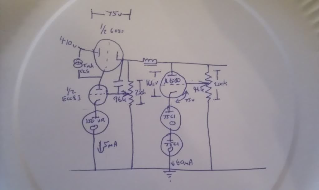
JamesD wrote:Previously I designed the attached psu for Dave Dove's RIAA amp using a TV dual triode It would have been better with a VR ref in their somewhere on the shunt but not sure that a 75V VR tube would work at these B+ volts... and , following this discussion the BG should come out!
This is a fantastic discussion to follow as you both give your thoughts and reasoning. And Paul, your accounts of your experience is wonderful! Many thanks to you both for doing this on the forum.
James
That last section in your diagram James is almost exactly what I was suggesting Steve tried, I think Nick 'nick-named' it the bouncy resistor, if you'll pardon the pun.
Analogue, the lost world that lies between 0 and 1.
Paul Barker wrote:Sorry Steve, but for me on paper it is a non starter. I don't do that much compromise.
Hi James.
Well usually as you know we don't think of everything at first, and in my case I often just build rather than write or talk, and adjust on test. We have to start somewhere some people on paper, me I see a picture in my head and build what I see. When I went to calculate the values for this circuit the flaws became apparent.
your circuit is all well and good for someone looking to regulate. In my life I eliminate caps that is the main purpose. If I wanted the bass of tight regulation I get that with choke input plentyfully. If I can tolerate caps I only need choke input. If I start regulating it is for the main purpose of eliminating as many as or all caps I can find.
It is still a fun little circuit to build, but that resistor needs attention. you could always use a high quality cap to return the whole AC signal loop and see this as just a regulator.
It's easy enough to separate the two roles as I already have a decent series reg running on the amplifier right now.
Only thing stopping me at the 'mo is the choke between the two stages.
I have various power chokes but it is the winding for HF that is throwing me.
I don't have the facilities or the expertise to wind my own.
I can do it no problem, the choke spec, now that's the bugbear.
where it does have legs is as the first stage of a two stage shunt reg following a series reg capacitor eliminator power supply.
What I have to do to eliminate caps is use loads of chokes and two very hefty shunt regulators. the use of this little circuit early on after the first choke, seperated from the final shunt valve with another choke would have the same effect and involve less iron.
SteveTheShadow wrote:It's easy enough to separate the two roles as I already have a decent series reg running on the amplifier right now.
Only thing stopping me at the 'mo is the choke between the two stages.
I have various power chokes but it is the winding for HF that is throwing me.
I don't have the facilities or the expertise to wind my own.
I can do it no problem, the choke spec, now that's the bugbear.
Just use a small resistor, or nothing at all.
Anode load chokes are suitable but you might have too much volt drop. Factor it into the design and you are fine.
All these power supplies have loads of volt drop stages to be factoredin and worked back. you end up with a high starting voltage.
You're right.
The limitation to the quality of the series reg is the voltage across the series pass valve. Primarily the compromise is the anode load on the error amplifier . The use of a CCS load for the error amplifier increases it's amplification factor. The total maximum available voltage change doesn't alter but the incremental amplification is vastly improved.
I had to use 75v across the series pass valve as this is a real design for a real situation. When designing a psu from scratch one would allow for 100v across the series pass.
Of course you adjust the wiper on the ecc83 grid until the volt drop across the series pass valve is what you want. you have the capability to vary the voltage but this is not designed as a multiple use power supply it is intended for a specific job. As you adjust for a lower volt drop you sacrifice quality, as you adjust for a greater volt drop you approach maximum dissipation of the series pass valve. If you change the voltage you incur penalties in the shunt element which follows. everything affects everything.