Right
For a Winter project I'm looking at experimenting with shunt regulators.
I would like to try a shunt reg for the HT to my 6B4G monoblocks and am thinking of using a triode-strapped 13E1 as the shunt element.
The voltages it likes to work at are exactly what I want out of a supply ie around 360V regulated.
Shunting twice the current of the output stage at 90mA is a walk in the park
for this tube as it has a 90W dissipation capability, plus it looks gorgeous, as
all who saw my power amp lit up will testify.
Trouble is I am clueless at the moment about how to design one to fulfil these requirements ie 360V out at 45mA.
Yep...I know I can stack two 0A2s and an 0B2 to get the rough voltage out
but after that I'm stuck.
I've had a look at Steve Bench's site so far but if anyone can point me to some other articles I'd be grateful, Most shunt regs I've seen via google
are only for phono stages or preamps. There does not seem to be a lot of stuff about power stages with shunt regulation applied.
Steve
Shunt Reg Using a 13E1 as Shunt Element
-
Cressy Snr

- Amstrad Tower of Power
- Posts: 10581
- Joined: Wed May 30, 2007 12:25 am
- Location: South Yorks.
-
IslandPink

- Amstrad Tower of Power
- Posts: 10041
- Joined: Tue May 29, 2007 7:01 pm
- Location: Denbigh, N.Wales
#2
Good luck and tell us how to do it Steve. I have a couple of 572B's waiting 
"Once you find out ... the Circumstances ; then you can go out"
#3
Hi Steve,
I shunted my 300B using the IXCY parts, the theory is the same for valves as MOSFETS.
http://www.tubecad.com/2007/01/blog0095.htm
http://www.tubecad.com/2007/06/blog0112.htm
http://www.tubecad.com/2007/06/blog0109.htm
there's more too on Broskie's site.
Andrew
I shunted my 300B using the IXCY parts, the theory is the same for valves as MOSFETS.
http://www.tubecad.com/2007/01/blog0095.htm
http://www.tubecad.com/2007/06/blog0112.htm
http://www.tubecad.com/2007/06/blog0109.htm
there's more too on Broskie's site.
Andrew
Last edited by Andrew on Thu Dec 22, 2011 9:22 pm, edited 1 time in total.
Analogue, the lost world that lies between 0 and 1.
#4
Here's what I was after....
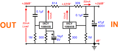
Feedforward & feedback shunt reg using a depletion mode mosfet, Swap mosfet for your valve, the size of load R (614 and 309 in this case) is approx 1/gm, if memory serves.
Andrew
Feedforward & feedback shunt reg using a depletion mode mosfet, Swap mosfet for your valve, the size of load R (614 and 309 in this case) is approx 1/gm, if memory serves.
Andrew
Analogue, the lost world that lies between 0 and 1.
-
Cressy Snr
- Amstrad Tower of Power
- Posts: 10581
- Joined: Wed May 30, 2007 12:25 am
- Location: South Yorks.
#5
Cheers Andrew
That's plenty of reading
That's plenty of reading
#6
Oh one more thing, JB missed this, important safety addition!
You need to add a zener diode across the cathode resistor to prevent the cathode voltage rising too high and the device conducting too much at start up. As it starts up the grid will be high too and you can end up in a zero bias failure mode as the shunt starts to conduct too much. I have a sim of this process somewhere, I also saw how, when I powered the shunt off a bench supply, the current limiter kicked in and the milliamp meter went off the scale as it started up.
All in all, in took me a while to figure out why I blew up at least one pair of shunts. And, right now, I don't see any reason why the zener wouldn't be a useful addition to a valve shunt even tho' a valve will take much more abuse before it dies. Having the zener will be much kinder to the valve concerned and its out of the circuit most of the time.
Andrew
Analogue, the lost world that lies between 0 and 1.
#7
There was once a 211 amp which also used 211 as the shunt reg tube. So if you could find that circuit you could adapt it. I may have read it in Sound Practices. I think the control of the shunt element was with solid state. I can't remember the author or the name of the amp.
-
Paul Barker

- Social Sevices have been notified
- Posts: 8987
- Joined: Mon May 21, 2007 9:42 pm
#8
"Development Notes on a Single Ended 211 Amplifier" Dennis Boyle and John Camille.
They put a 211 at the B+ with the equivalent cathode arrangement as the output valve. They controlled the grid of the shunt valve with solid state. So far I have only found the bare sketch. It was a later article where they detailed the solid state control element.
I have spelled out Steve Benches method using class A2 valves in other threads. Controlling negative bias valves is more complicated. You could do it in the same simple way by placing the VR tube on the cathode of the 13e1 and grounding the grid. But the VR tube to qualify would have to be of sufficient low voltage (AFAIK 75v is lowest) and it would pass the same current as the 13e1.
I will keep digging through the archives in case I turn up the explanation article.
-
Paul Barker
- Social Sevices have been notified
- Posts: 8987
- Joined: Mon May 21, 2007 9:42 pm
#9
Ok it is Sound Practices Summer 1994.
I have just done a quick sweep of the crux of it. Basicaly it is full of concepts I avoid. Loads of error correction by means of feedback using zenners and opamps.
They do point out in their article, (though they didn't blame themselves) that most people didn't like this 211 amp on the Edgar Horns.
Their excuse was that you only need 50mW to 500mW of music power. Now they claim that some nasty artifacts from zenners and solid state used in the recording chain are revealed by their marvelously perfect amplifier, and because of their extreme capability their amp is showing up nasty sounds elsewhere.
I would suggest to take a look at the opamps and zenners on the grid of their shunt valve aswell as those in the recording chain!
I don't think one is allowed to publish this actual article, but I might be able to "lend" it to a friend Steve by electronic means. Be your own judge.
Paul
Last edited by Paul Barker on Fri Dec 23, 2011 10:16 am, edited 1 time in total.
-
Cressy Snr
- Amstrad Tower of Power
- Posts: 10581
- Joined: Wed May 30, 2007 12:25 am
- Location: South Yorks.
#10
Paul you have a PM 
Steve
Steve
-
Paul Barker
- Social Sevices have been notified
- Posts: 8987
- Joined: Mon May 21, 2007 9:42 pm
#11
you have email.
-
Paul Barker
- Social Sevices have been notified
- Posts: 8987
- Joined: Mon May 21, 2007 9:42 pm
#12
To be fair to them and brutally honest to myself, I too experience this when listening to some music.Paul Barker wrote: they claim that some nasty artifacts from zenners and solid state used in the recording chain are revealed by their marvelously perfect amplifier, and because of their extreme capability their amp is showing up nasty sounds elsewhere.
As you mostly know I have fully shunt regulated power supply choke input because there are no caps.
Yes I too find that small thin films of cloud are removed after you get your output stage unadulterated by the tone of capacitors and you reduce the ac signal down to another valve vertually completely. (yes I found some tone was coming from capacitors in the power supply after I removed them all else remaining equal.
BUT I imediately all of a sudden found with the extreme extra detail something which made me tired.
This was fixed by shanging the opamp in the cheap ebay dac to a burr brown.
-
Paul Barker
- Social Sevices have been notified
- Posts: 8987
- Joined: Mon May 21, 2007 9:42 pm
#13
Poor old Steve is probably wading through that article now which is not exactly user friendly. But it was seminal for 1994.
Myself I would be thinking of a simpler solution.
Myself I would be thinking of a simpler solution.
-
Cressy Snr
- Amstrad Tower of Power
- Posts: 10581
- Joined: Wed May 30, 2007 12:25 am
- Location: South Yorks.
#14
Jeez I managed to get through it but I'm afraid I almost lost the will to livePaul Barker wrote:Poor old Steve is probably wading through that article now which is not exactly user friendly. But it was seminal for 1994.
Myself I would be thinking of a simpler solution.
And you're right Paul
I'm thinking of a simpler solution.
I'll post my ideas a bit later on so you can point and laugh
Steve
#15
The 45 stage of my old 211 amp used a 13E1 as a shunt. It was based on the SB site and used (I think) a ecc83 as a LTP error amp.
Whenever an honest man discovers that he's mistaken, he will either cease to be mistaken or he will cease to be honest.