Shunt Reg Using a 13E1 as Shunt Element
-
Paul Barker

- Social Sevices have been notified
- Posts: 8991
- Joined: Mon May 21, 2007 9:42 pm
#46
How come you need 360v? Is your amp direct coupled?
-
Paul Barker
- Social Sevices have been notified
- Posts: 8991
- Joined: Mon May 21, 2007 9:42 pm
#47
Anyway I have just thought of a brilliant plan. Build an output stage of 12e1 with a 75c1 as it's cathode bias and complement that with a shunt valve the same. So either side of the transformer primary two identical setups will see saw.
But for simplicity of construction the power supply will be LCLC prior to this rather than series reg. That way I can make it quite quickly.
But for simplicity of construction the power supply will be LCLC prior to this rather than series reg. That way I can make it quite quickly.
#48
I haven't worked out how to do it, but I think a push pull output stage would be the best of both worlds. top valve acting as a series reg, bottom one as a shunt. Needs something not unlike a OTL amp as the power supply.
Whenever an honest man discovers that he's mistaken, he will either cease to be mistaken or he will cease to be honest.
-
Cressy Snr

- Amstrad Tower of Power
- Posts: 10582
- Joined: Wed May 30, 2007 12:25 am
- Location: South Yorks.
#49
No It runs into a 5K secondary rather than the usual 2A3 impedance of 2.5KPaul Barker wrote:How come you need 360v? Is your amp direct coupled?
It operates more like a souped-up 45.
There's 300V across the valve, running at around 40 odd mA. 60V cathode bias. It swings lots of volts to make the power back up it would normally lose which leads on to the hefty hi-gain, hi-current pentode kicking its backside: a pentode that would usually be biased this hot to drive a 300B not a 2A3.
The concept works beautifully
-
Paul Barker
- Social Sevices have been notified
- Posts: 8991
- Joined: Mon May 21, 2007 9:42 pm
#50
I did some experiments and the tube is in cut off at what I extrapolated. There is little useful info on web about triode mode 12e1, but it is not happening with -75v bias. So the whole 75v vr on cathode is bad idea. Sorry Steve, it will have to be a negative supply.Laurence wrote:Just mulling this over, the 12E1 Triode connected would have a max g2 voltage 300 max current 100 mA max dissipation 35 Watts. Be less hungry for filament and less likely to create the problems Nick experienced. Colomore used to have bucket loads of these and tried touting them as TT22 alternatives. But they were meant for series pass regulators.
These triode curves
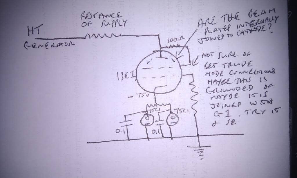
are all that I could find but if you extrapolate from them it could be that it would be well worth just plugging it in triode connected with a single 75C1 on the cathode, as in Paul'sdiagram above, but with just one 75C1, and see just what current it pulls from a 360v supply.Paul Barker wrote:
As Paul says don't be obsessive about the voltage and current just try this and see where it takes you. then work out some adjustments if necessary.
In my estimation at the 285 plate volts 360v B+ and a 75v VR would cause the current would be shy of your 45mA. But how shy is for experiment. If it is very shy then you could use two 12e1's and depending where the combined current takes you either one or two VR's. Time for some trials.

-
Paul Barker
- Social Sevices have been notified
- Posts: 8991
- Joined: Mon May 21, 2007 9:42 pm
#51
I did some experiments and the tube is in cut off at what I extrapolated. There is little useful info on web about triode mode 12e1, but it is not happening with -75v bias. So the whole 75v vr on cathode is bad idea. Sorry Steve, it will have to be a negative supply.Laurence wrote:Just mulling this over, the 12E1 Triode connected would have a max g2 voltage 300 max current 100 mA max dissipation 35 Watts. Be less hungry for filament and less likely to create the problems Nick experienced. Colomore used to have bucket loads of these and tried touting them as TT22 alternatives. But they were meant for series pass regulators.
These triode curves
are all that I could find but if you extrapolate from them it could be that it would be well worth just plugging it in triode connected with a single 75C1 on the cathode, as in Paul'sdiagram above, but with just one 75C1, and see just what current it pulls from a 360v supply.Paul Barker wrote:
As Paul says don't be obsessive about the voltage and current just try this and see where it takes you. then work out some adjustments if necessary.
In my estimation at the 285 plate volts 360v B+ and a 75v VR would cause the current would be shy of your 45mA. But how shy is for experiment. If it is very shy then you could use two 12e1's and depending where the combined current takes you either one or two VR's. Time for some trials.
-
Cressy Snr
- Amstrad Tower of Power
- Posts: 10582
- Joined: Wed May 30, 2007 12:25 am
- Location: South Yorks.
#52
Ah well 
-
Paul Barker
- Social Sevices have been notified
- Posts: 8991
- Joined: Mon May 21, 2007 9:42 pm
#53
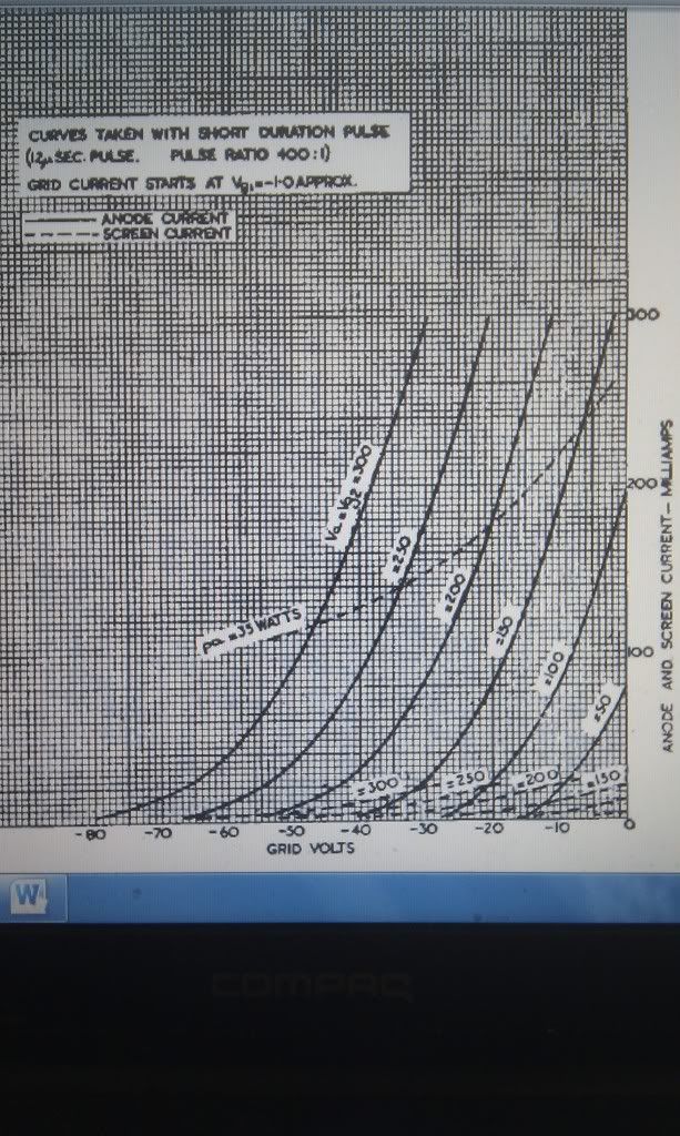
More appropriate here. I have returned to playing with the 12e1 as shunt device on paper. the following Beam Tetrode curves are the most useful for the calculations we have to make.
From the outset let's just say that as a shunt regulator it is far better operated as a beam tetrode because:
Say the voltage on the B+ drops this is sensed and applied directly to the grid. the cathode is held firmly at the fixed voltage. The change in grid ref to cathode results in a massive momentory reaction by changing the currnt pulled by the valve. the regulating effect of this on the power supply is that the different curren pull on the resistance of the power supply changes the voltage.
As a triode the effect is much less pronounced.
Short speak it is the transconductance which improves the regulation Beam tetrode mode this valve has a gm of 14. Compare that with the 6080 triode we have been playing with which has a gm of 6.5.
So if we restrict ourselves to a single 75C1 voltage reference and hence a current of 60mA we can hold a range of voltages with that current pull from 275v to 450v controlling the grid from -28v to -3v with the screen grid held at 150v by a VR.
It is very important that we don't protect the VR tube with a CCS set at 60mA because that will prevent the correct operation. so we must understand what we are working with. we must have a good idea of our starting point and we make sure that our supply is one which when 60mA is pulled down on it the desired B+ voltage will be achieved. Personally I calculate the shunt pull by measuring the current pull across a choke (by calculation from volt drop) and deduct the amplifier current. If you want put a 1 ohm resistor on the cathode of VR volt drop across it in mV is current in mA.
-
Cressy Snr
- Amstrad Tower of Power
- Posts: 10582
- Joined: Wed May 30, 2007 12:25 am
- Location: South Yorks.
#54
Well Paul
The 75C1s arrived this morning with your test results.
Thanks for taking the trouble to match them up.
My 12E14s await (in tetrode mode by the looks of things)
As I said in the 2A3 monoblock thread, Demanding more quiescent current from the PSU could compromise PSU headroom.
OTOH it is capable of half-an-amp at full chat, as it was originally designed for the 13E1 amp.
Must resist the urge to mess about...........must resist the urge to mess about...Must not talk myself into things
-
Cressy Snr
- Amstrad Tower of Power
- Posts: 10582
- Joined: Wed May 30, 2007 12:25 am
- Location: South Yorks.
#55
Oh sod it!....let's get on with it.
-
Paul Barker
- Social Sevices have been notified
- Posts: 8991
- Joined: Mon May 21, 2007 9:42 pm
#56
right so is your desired HT voltage still 360v?
-
Cressy Snr
- Amstrad Tower of Power
- Posts: 10582
- Joined: Wed May 30, 2007 12:25 am
- Location: South Yorks.
#57
I can get away with 340V, running the output stage at 40mA. It sounds no different.Paul Barker wrote:right so is your desired HT voltage still 360V?
Interestingly I have been experimenting with the driver stage by reducing the current through it.
The 150V screen voltage has been reduced to 108V with a 0B2 replacing an 0A2. The results have been very good.
-
Paul Barker
- Social Sevices have been notified
- Posts: 8991
- Joined: Mon May 21, 2007 9:42 pm
#58
Anyway how you work it out using that chart above is this.
Those 45 degree lines with a confusing nomenclature are interpreted as follows. The number for example 150 means the product of Anode voltage less Screen voltage.
So I calculated to 360v deduct the 75v VR you have an anode voltage of 285 deduct the screen voltage 150 (we chose to use 150 we could have chosen any figure we liked but we are given helpfull information for 150) and you are working to an imaginary line parallel to the others the 135v line. Draw a horisontal line at 60mA where this crosses the imaginary 135v line draw a vertical line for the grid voltage. Without geting a ruler out it looks like -19v to me. The screen grid current for the 150v screen voltage looks around 4mA.
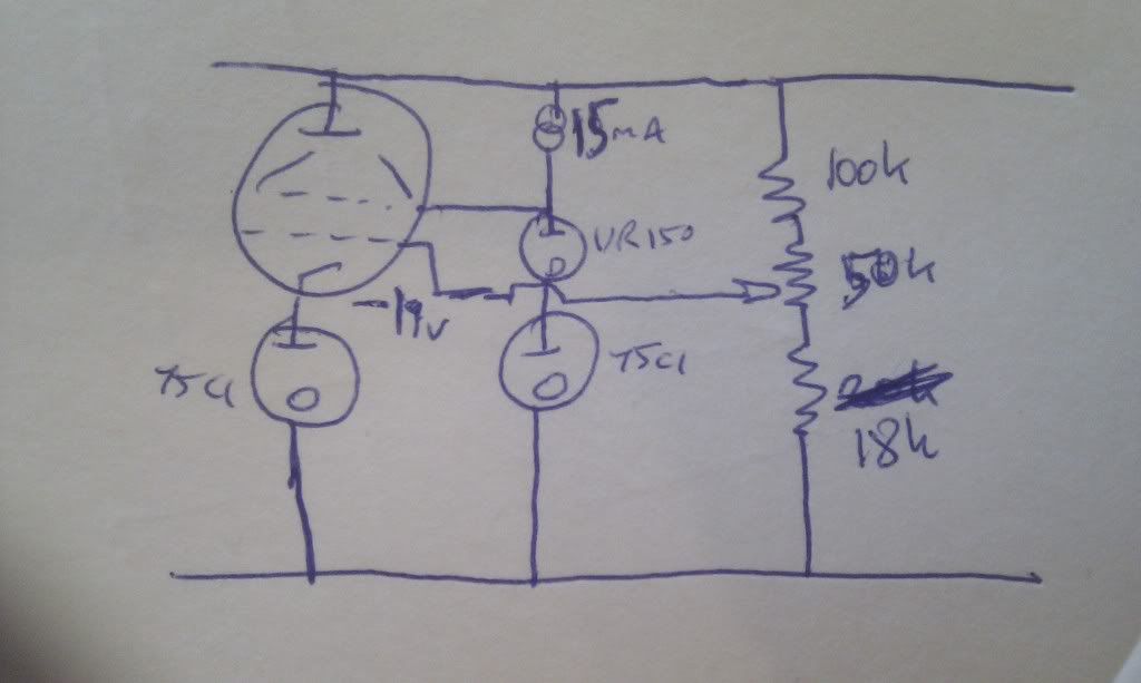
screen VR looses 4mA from B+ to the screen grid contribution to total shunt valve current of 60mA. Therefore we need to bleed 15mA from the supply so that a healthy 10 mA keeps the VR alight. We could sacrifice some of our regulator valve current and just use a VR150 with cathode on the valve cathode and a current set resistor (or ccs) calculated for 15mA. It would take one less VR tube but some of the 60mA would be not as well regulated. But that is extreme pedanticism.
Those 45 degree lines with a confusing nomenclature are interpreted as follows. The number for example 150 means the product of Anode voltage less Screen voltage.
So I calculated to 360v deduct the 75v VR you have an anode voltage of 285 deduct the screen voltage 150 (we chose to use 150 we could have chosen any figure we liked but we are given helpfull information for 150) and you are working to an imaginary line parallel to the others the 135v line. Draw a horisontal line at 60mA where this crosses the imaginary 135v line draw a vertical line for the grid voltage. Without geting a ruler out it looks like -19v to me. The screen grid current for the 150v screen voltage looks around 4mA.
screen VR looses 4mA from B+ to the screen grid contribution to total shunt valve current of 60mA. Therefore we need to bleed 15mA from the supply so that a healthy 10 mA keeps the VR alight. We could sacrifice some of our regulator valve current and just use a VR150 with cathode on the valve cathode and a current set resistor (or ccs) calculated for 15mA. It would take one less VR tube but some of the 60mA would be not as well regulated. But that is extreme pedanticism.
-
Cressy Snr
- Amstrad Tower of Power
- Posts: 10582
- Joined: Wed May 30, 2007 12:25 am
- Location: South Yorks.
#59
Cheers Paul
That looks great
That looks great
-
Cressy Snr
- Amstrad Tower of Power
- Posts: 10582
- Joined: Wed May 30, 2007 12:25 am
- Location: South Yorks.
#60
Cheers Paul
That looks great
I only had two 150V tubes but throwing both of them spare with the 12HG7 current reduction has made them available for this circuit.
That looks great
I only had two 150V tubes but throwing both of them spare with the 12HG7 current reduction has made them available for this circuit.