Shunt Reg Using a 13E1 as Shunt Element
-
Cressy Snr

- Amstrad Tower of Power
- Posts: 10579
- Joined: Wed May 30, 2007 12:25 am
- Location: South Yorks.
#16
Did you sit the error amp on a negative supply Nick?
-
Paul Barker

- Social Sevices have been notified
- Posts: 8985
- Joined: Mon May 21, 2007 9:42 pm
#17 Re: Shunt Reg Using a 13E1 as Shunt Element
I am trying to help you with a simple method, but you have lost me. Are you wanting to use two 13e1's? at 45mA each?
Looking at the triode curves of the 13e1 I would begin an experiment of this nature. It is likely that the outcome may provide either more current pull than 90mA if it is to definately work to 360v or if you can cope with 375v quite likely it would stabilise in the right region of your desire.
It is far better to 'sperymint first hand and adapt desires than to force such a design to comply by use of complexity. This above method avaoids the negative supply. You could very crudely balance the VR's by brightness to the human eye, or you could be kinder to them and put sense resistors on each kathode.
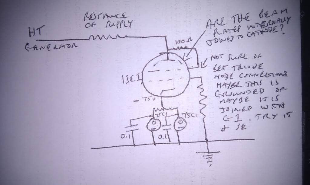
If you must be exact about the outcome then with a -105v supply you can have 0 to -105v of adjustment on the grid as below.
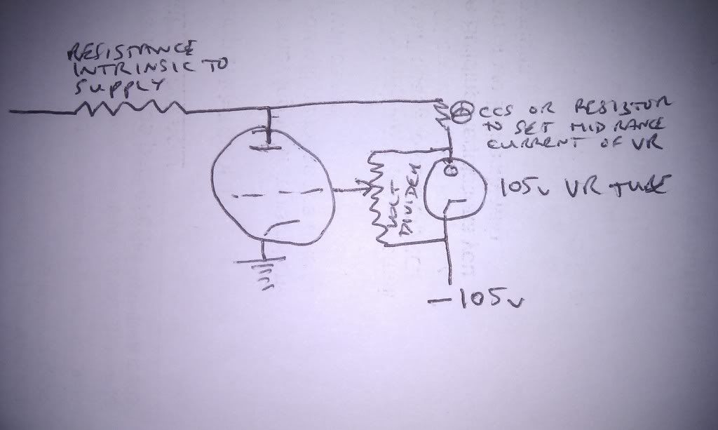
The latter provides more scope. The actual HT voltage can be adjusted by use of resistance prior to this stage and the other elements like transformer and rectifier. The current pull of 13e1 and voltage it settles at is adjusted by the resistive defider across the VR. Should greater volatge range be required use a 150v VR and -150v supply.
Your negative supply must provide the current through the VR plus the current through the voltage devider. Keep the negative supply stiff or else it will limit the tightness of control the VR provides.
In both cases the benefit of the VR tube over resistances to set the voltages is that it actively repells the affect of varying currents from the output stage on the grid of the shunt valve, thus keeping it stiffly controlled. But it has less pathways through which the control circuit has to spend time before the error is corrected. Hence it is less like feedback and purer in application to the principles of simplicity. The majority of the audio ac return path it is hoped passes straight through the triode (13e1) but listening experience tells me the capacitors in the supply prior to this stage do make a contribution to the sound and it is quite likely so does the active component (in this case VR) so we have to see the a3e1 as passing some or most of the ac signal but in parallel with every other item which shunts from B+ to ground. It's other purpose; stiff supply voltage, would be better controlled with complexed amplification of error signal but in my view unnecesary, particularly if the whole show starts at choke input.
If you want 90mA then it is not beyond the realms of possibility that everything would fall into place (personally if it didn't provide exact voltage, what it provides would become my voltage) using a parallel pair of 75c1's on the cathode balanced with resistors or CCS's.SteveTheShadow wrote: 360V regulated.
Shunting twice the current of the output stage at 90mA is a walk in the park
for this tube as it has a 90W dissipation capability.
Trouble is I am clueless at the moment about how to design one to fulfil these requirements ie 360V out at 45mA.
Looking at the triode curves of the 13e1 I would begin an experiment of this nature. It is likely that the outcome may provide either more current pull than 90mA if it is to definately work to 360v or if you can cope with 375v quite likely it would stabilise in the right region of your desire.
It is far better to 'sperymint first hand and adapt desires than to force such a design to comply by use of complexity. This above method avaoids the negative supply. You could very crudely balance the VR's by brightness to the human eye, or you could be kinder to them and put sense resistors on each kathode.
If you must be exact about the outcome then with a -105v supply you can have 0 to -105v of adjustment on the grid as below.
The latter provides more scope. The actual HT voltage can be adjusted by use of resistance prior to this stage and the other elements like transformer and rectifier. The current pull of 13e1 and voltage it settles at is adjusted by the resistive defider across the VR. Should greater volatge range be required use a 150v VR and -150v supply.
Your negative supply must provide the current through the VR plus the current through the voltage devider. Keep the negative supply stiff or else it will limit the tightness of control the VR provides.
In both cases the benefit of the VR tube over resistances to set the voltages is that it actively repells the affect of varying currents from the output stage on the grid of the shunt valve, thus keeping it stiffly controlled. But it has less pathways through which the control circuit has to spend time before the error is corrected. Hence it is less like feedback and purer in application to the principles of simplicity. The majority of the audio ac return path it is hoped passes straight through the triode (13e1) but listening experience tells me the capacitors in the supply prior to this stage do make a contribution to the sound and it is quite likely so does the active component (in this case VR) so we have to see the a3e1 as passing some or most of the ac signal but in parallel with every other item which shunts from B+ to ground. It's other purpose; stiff supply voltage, would be better controlled with complexed amplification of error signal but in my view unnecesary, particularly if the whole show starts at choke input.
Last edited by Paul Barker on Fri Dec 23, 2011 5:13 pm, edited 5 times in total.
-
Cressy Snr
- Amstrad Tower of Power
- Posts: 10579
- Joined: Wed May 30, 2007 12:25 am
- Location: South Yorks.
#19 Re: Shunt Reg Using a 13E1 as Shunt Element
Nope just a single one.Paul Barker wrote:I am trying to help you with a simple method, but you have lost me. Are you wanting to use two 13e1's? at 45mA each?
Maybe I have the wrong end of the stick but I thought you needed the shunt element to be capable of shunting twice the current you would need to work the output stage. That's the part I'm confused about.
So I suppose my question is...given those requirements do you configure the 13e1 to shunt 45ma and rely on its large dissipation value to handle an off load condition or do you actually configure it for 90mA, then draw 45ma through the output stage whilst it shunts the other 45mA to ground.
Or if you configure 90mA is the 13E1 going to shunt its 90mA regardless whilst the output stage draws another 45mA from the supply making a total of 135mA coming together at the ground node.
I think I might have got me Kirchoff mixed up somewhere along the line
and it's that that's throwing me.
Thanks for the help so far Paul, much appreciated
Steve
-
Paul Barker
- Social Sevices have been notified
- Posts: 8985
- Joined: Mon May 21, 2007 9:42 pm
#20 Re: Shunt Reg Using a 13E1 as Shunt Element
This will do. So your power supply has to provide 90mA.SteveTheShadow wrote: So I suppose my question is...given those requirements do you configure the 13e1 to shunt 45ma and rely on its large dissipation value to handle an off load condition or do you actually configure it for 90mA, then draw 45ma through the output stage whilst it shunts the other 45mA to ground.
Steve
For your 13e1 to shunt 45 mA rather than 90mA probably requires a more negative bias than I was exampleing above. I would go with the negative supply and a 150v VR tube so you have capability to adjust on test.
-
Cressy Snr
- Amstrad Tower of Power
- Posts: 10579
- Joined: Wed May 30, 2007 12:25 am
- Location: South Yorks.
#21 Re: Shunt Reg Using a 13E1 as Shunt Element
Cheers PaulPaul Barker wrote:This will do. So your power supply has to provide 90mA.SteveTheShadow wrote: So I suppose my question is...given those requirements do you configure the 13e1 to shunt 45ma and rely on its large dissipation value to handle an off load condition or do you actually configure it for 90mA, then draw 45ma through the output stage whilst it shunts the other 45mA to ground.
Steve
For your 13e1 to shunt 45 mA rather than 90mA probably requires a more negative bias than I was exampleing above. I would go with the negative supply and a 150v VR tube so you have capability to adjust on test.
I suspected I had messed up with the current requirements
I feel I'm getting somewhere now
-
Paul Barker
- Social Sevices have been notified
- Posts: 8985
- Joined: Mon May 21, 2007 9:42 pm
#22
I do believe it will be nice. The 13e1 has a major advantage of high transconductance which suits it to this purpose.
#23
Though high gm reminds me, the ones I had (thanks Paul) were very happy being a source of RF, in fact they did very well at being a plasma tweeter, lots of hissing and spitting and upset multimeters if anywhere close.
Whenever an honest man discovers that he's mistaken, he will either cease to be mistaken or he will cease to be honest.
-
Paul Barker
- Social Sevices have been notified
- Posts: 8985
- Joined: Mon May 21, 2007 9:42 pm
#24
Could pose a problem.
-
Cressy Snr
- Amstrad Tower of Power
- Posts: 10579
- Joined: Wed May 30, 2007 12:25 am
- Location: South Yorks.
#25
Yes I think it will work nicely with the negative supply.Paul Barker wrote:I do believe it will be nice. The 13e1 has a major advantage of high transconductance which suits it to this purpose.
Looks like between about -95 and -100V grid bias will give 45mA through the 13E1, at around my required output voltage, so an 0D3 as the VR tube part of the control element should do very nicely.
-
Paul Barker
- Social Sevices have been notified
- Posts: 8985
- Joined: Mon May 21, 2007 9:42 pm
#26
It would be good but remember that by controlling as triode grid with the vr tube either on the cathode or the grid the effect is the same. It is amplified by the transconductance of the triode. so the regulation is made tighter by the use of the triode.
Remember what transconductance is. It is the amount by which anode current is varied through a 1v change in grid voltage. therefore the greater the transconductance of the regulator triode the greater will be it's affect on the output voltage in response to a change in the output voltage. Or put it another way any variation it clamps down on extra powerfully! This is a more direct response than one where there is an amplifier valve used first to increase the reaction to a change in voltage. It is one stage less in the time laps from voltage change to response.
Remember what transconductance is. It is the amount by which anode current is varied through a 1v change in grid voltage. therefore the greater the transconductance of the regulator triode the greater will be it's affect on the output voltage in response to a change in the output voltage. Or put it another way any variation it clamps down on extra powerfully! This is a more direct response than one where there is an amplifier valve used first to increase the reaction to a change in voltage. It is one stage less in the time laps from voltage change to response.
-
Cressy Snr
- Amstrad Tower of Power
- Posts: 10579
- Joined: Wed May 30, 2007 12:25 am
- Location: South Yorks.
#27
Just been exploring around the Interweb and have found some fascinating old gas regulators listed.
I mean tubes such as the giant 100E1 neon regulator at 50-200mA at 100V and the AW3/S130 old British neon 120V 75mA tubes. All hefty blighters.
Three S130s in series across my PSU with a suitable current limiting resistor and Bob's 'yer uncle....360V at 45mA
Too simple probably. Noisy b'stards I'll bet and my existing series reg would no doubt easily outperform them.
Interesting though and they wouldn't half look cool.
-
Paul Barker
- Social Sevices have been notified
- Posts: 8985
- Joined: Mon May 21, 2007 9:42 pm
#28
Well it would be interesting to try as there is no heater supply required. I would put the current set resistor in series with the power supply and make the node of the VR tubes and the output transformer direct. This is to minimise the resistance of the AC signal return path and isolate to some extent the power supply from the AC path. Though as I said before it is parallel to some degree.
My favourite is the 75C1 because it can do 60mA and it is a low voltage so you have more flexibility when series connecting them. For the final variation you can use one of the British 4 pin ones you mention to retain the current capability. I have found the coloured 75C1 to be very tough, none have ever failed me, whereas the purple coloured popular 9 pin VR's I have often found to be weak and not very stiff as regulators. As stated previously all VR tubes have to be tested on a rig and swept through their current range to establish how strong they are, their variation across the range, and their actual voltage at your known current.
My favourite is the 75C1 because it can do 60mA and it is a low voltage so you have more flexibility when series connecting them. For the final variation you can use one of the British 4 pin ones you mention to retain the current capability. I have found the coloured 75C1 to be very tough, none have ever failed me, whereas the purple coloured popular 9 pin VR's I have often found to be weak and not very stiff as regulators. As stated previously all VR tubes have to be tested on a rig and swept through their current range to establish how strong they are, their variation across the range, and their actual voltage at your known current.
#29
Just mulling this over, the 12E1 Triode connected would have a max g2 voltage 300 max current 100 mA max dissipation 35 Watts. Be less hungry for filament and less likely to create the problems Nick experienced. Colomore used to have bucket loads of these and tried touting them as TT22 alternatives. But they were meant for series pass regulators.
These triode curves

are all that I could find but if you extrapolate from them it could be that it would be well worth just plugging it in triode connected with a single 75C1 on the cathode, as in Paul's
As Paul says don't be obsessive about the voltage and current just try this and see where it takes you. then work out some adjustments if necessary.
In my estimation at the 285 plate volts 360v B+ and a 75v VR would cause the current would be shy of your 45mA. But how shy is for experiment. If it is very shy then you could use two 12e1's and depending where the combined current takes you either one or two VR's. Time for some trials.
These triode curves
are all that I could find but if you extrapolate from them it could be that it would be well worth just plugging it in triode connected with a single 75C1 on the cathode, as in Paul's
diagram above, but with just one 75C1, and see just what current it pulls from a 360v supply.Paul Barker wrote:
As Paul says don't be obsessive about the voltage and current just try this and see where it takes you. then work out some adjustments if necessary.
In my estimation at the 285 plate volts 360v B+ and a 75v VR would cause the current would be shy of your 45mA. But how shy is for experiment. If it is very shy then you could use two 12e1's and depending where the combined current takes you either one or two VR's. Time for some trials.
-
Paul Barker
- Social Sevices have been notified
- Posts: 8985
- Joined: Mon May 21, 2007 9:42 pm
#30
Might just fall into place. I think Steve has some 12e1's, if not I can send some.
One consideration of the SP 211 amp is the use of 211 to return ac. We so often neglect to realise that the other (b+) side of the opt in a se amp has as much influence on Sound . Same valve as output valve makes sense. Food for thought.
I can feel a new 211 amp in my bones.
One consideration of the SP 211 amp is the use of 211 to return ac. We so often neglect to realise that the other (b+) side of the opt in a se amp has as much influence on Sound . Same valve as output valve makes sense. Food for thought.
I can feel a new 211 amp in my bones.