Can anyone help, please? I recently bought a second hand bb100 with a full complement of beard valves, it was said to be fully serviced with new valves. I have barely used it and I am now having a problem, two of the EL84 valves which are sat on the right side at the back; (side by side) are starting to glow very red. They look quite angry. Can anyone give me any advice at all, it would be greatly appreciated. And all so can anyone refer me to a good valve amp DR, in the Yorkshire area.
PS. This is my first step into the valve world so as you can imagine I am totally green.
The amp when running sounds fantastic.
Thank you all in advance.
Paul
Bill Beard BB100 'HELP' pleas

#2
Hi Pault,
Our revered host Nick Gorham is the Valve Doctor you are seeking. He lives just outside Halifax so in your neck of the woods.
Unfortunately Nick, along with a lot of other forum members, is over at Owston DIY meet this weekend, just outside Doncaster.
I'm sure he will pick up on this thread and sort the amp for you.
#4
I dont know of any available circuits for the beard amps, but with a bit of tracing it should be possible to work it out. Are there any bias adjustments on the amp? if so I would guess it just needs adjusting, if not it may be a failed cathode cap, or leaky coupling cap.
Whenever an honest man discovers that he's mistaken, he will either cease to be mistaken or he will cease to be honest.
-
Mike H

- Amstrad Tower of Power
- Posts: 20189
- Joined: Sat Oct 04, 2008 5:38 pm
- Location: The Fens
- Contact:
#5
By way of an explanation, those EL84's are passing too much current which is literally making them red hot
"No matter how fast light travels it finds that the darkness has always got there first, and is waiting for it."
#6
Just if folk are interested. I have this amp on the bench now. Nothing seems to be broken, but two of the valves are certainly passing more current. I will know more tonight, I had to get a new bag of 500ma fuses, as the amp keeps blowing fuses whenever a valve arcs over.
Its hard to say just what the original plan was with the amp, but I suspect its to sell a lot of replacement el84's. It seems to be designed to run them at 390v on the anode and screen and at about 36ma a valve, so by my thoughs thats just shy of 14w a valve, or 116% of max dissapation. Its into Vox AC30 op points. Its mixed bias, so the only thing keeping the valves in some sort of balance is a 33R in each cathode. Given there are THREE pairs of valves per chan, I can only assume they spent a lot of time balancing up sets of replacements.
My plan is to reduce the standing current by increasing the bias and see just how balanced the valves are, it may be possible to get it working with lower standing current, but I suspect it may need a new set of valves, at least for that chan.
Each valve does have a led that is meant to indicate a valve passing too much current, so maybe you are meant to have a bag of spares and just replace them as the led lights up.
Whenever an honest man discovers that he's mistaken, he will either cease to be mistaken or he will cease to be honest.
#8
the history jargon on the web site says he's sailing round the world on his luxury yacht.........just how many el84 sales does it take to enter the luxury yacht fraternity!
mmmmm
just thought of a lame joke...how many el84s does it take to make 50watts
mmmmm
just thought of a lame joke...how many el84s does it take to make 50watts
There's nowhere you can be that isn't where you're meant to be
-
Dave the bass

- Amstrad Tower of Power
- Posts: 12276
- Joined: Tue May 22, 2007 4:36 pm
- Location: NW Kent, Darn Sarf innit.
#9
Poor likkle valvesLee S wrote:Poor design in other words Nick... Caning the valves to within an inch of their lives.... Nice.... Not !!
DTB
"The fat bourgeois and his doppelganger"
#10
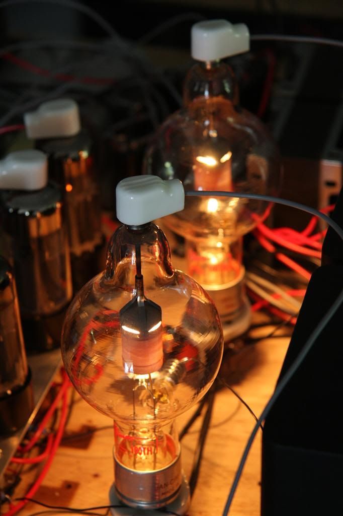
Before you accuse me of mistreating valves young man, I will point out that those valves were running at less than 33% of max anode voltage, and only 85% of plate dissipation.Dave the bass wrote:Poor likkle valvesLee S wrote:Poor design in other words Nick... Caning the valves to within an inch of their lives.... Nice.... Not !!
DTB
Whenever an honest man discovers that he's mistaken, he will either cease to be mistaken or he will cease to be honest.
-
Dave the bass
- Amstrad Tower of Power
- Posts: 12276
- Joined: Tue May 22, 2007 4:36 pm
- Location: NW Kent, Darn Sarf innit.
#11
Nick wrote:
Before you accuse me of mistreating valves young man, I will point out that those valves were running at less than 33% of max anode voltage, and only 85% of plate dissipation.
Yes, I know they're self gettering and all that but I'm sureI can see the tears coming from that valve... or is it sweat?
DTB
"The fat bourgeois and his doppelganger"
-
Dave the bass
- Amstrad Tower of Power
- Posts: 12276
- Joined: Tue May 22, 2007 4:36 pm
- Location: NW Kent, Darn Sarf innit.
#12
You (Nick) just inspired me to look at the Data sheet for the 100TH.
 Blimey.
...Max Plate voltage 3KV, Max plate current almost 1/4 of an amp and anode dissipation of 100W!
'Maximum signal peak driving power 18W' @ 1.5KV anode voltage.
If I've got that right does that mean that for the given max AF voltage i/p of 145V to the grid there's just over 103mA of grid current flowing? That'd be 15W or so of Grid dissipation wouldn't it? I know at Owster's you said they're designed to allow grid current to flow.
DTB
"The fat bourgeois and his doppelganger"
#13
heh! just don't encourage him thasall!!Dave the bass wrote:You (Nick) just inspired me to look at the Data sheet for the 100TH.
DTB
There's nowhere you can be that isn't where you're meant to be
#14
Yep, max grid dissipation is 20W, thats why there is a heat sync on the grid connection.Dave the bass wrote:You (Nick) just inspired me to look at the Data sheet for the 100TH.
...Max Plate voltage 3KV, Max plate current almost 1/4 of an amp and anode dissipation of 100W!
'Maximum signal peak driving power 18W' @ 1.5KV anode voltage.
If I've got that right does that mean that for the given max AF voltage i/p of 145V to the grid there's just over 103mA of grid current flowing? That'd be 15W or so of Grid dissipation wouldn't it? I know at Owster's you said they're designed to allow grid current to flow.
DTB
Told you I was letting the valve have it easy
Whenever an honest man discovers that he's mistaken, he will either cease to be mistaken or he will cease to be honest.
-
Mike H
- Amstrad Tower of Power
- Posts: 20189
- Joined: Sat Oct 04, 2008 5:38 pm
- Location: The Fens
- Contact:
#15
EEEEEK!!!Nick wrote:I suspect its to sell a lot of replacement el84's. It seems to be designed to run them at 390v on the anode and screen and at about 36ma a valve
No naughty mustn't
How about converting to cathode bias? As there's obviously enough HT for it.
"No matter how fast light travels it finds that the darkness has always got there first, and is waiting for it."