Page 1 of 1
#1 AD797 OPAMP input to a grounded grid valve stage question
Posted: Fri Jun 13, 2014 10:30 am
by Paul Barker
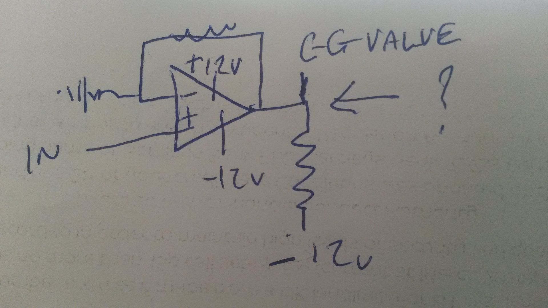
Opamp load resistor will have to sink the GG stage current to the -12v rail. (I have elected for +/- 12v so I can use batteries.
The question is how critical is the Opamp of a slight offset on it's output?
If it is critical then I see a solution of Constant Current load for the GG valve then a tight tolerance opamp load resistor. This bias of the valve could be fixed so it will absorb any unexpected in it's plate voltage. As seen on the left diagram below. Whereas I would prefer to use the right diagram. But with the right diagram the valve could alter the output voltage potential of the opamp as it shifts, and it would have to be fine tuned in original set up.
#2
Posted: Sat Jun 14, 2014 10:44 pm
by jack
Off the top of my head, the output of the 797 will not like this - in this configuration, it will be continually trying to compensate for the output offset - I suspect that it'll just get hot and be unhappy.
I've used the 797 in a number of applications (metal detectors, ultra-low-noise amps, my Quad 405-2 rebuild etc.) and its a good chip, sourcing up to 50mA, but I'm not convinced by your proposal.
What are you trying to achieve here?
#3
Posted: Sat Jun 14, 2014 11:03 pm
by Paul Barker
Looking at grounded grid options.
Thanks for answering.
I have a lot of objectives in my head, but you have helped me on the way.
I am thinking then, that if I use ccs load on the GG valve adjusted to set the level at the opamp out, and a precision resistor as the opamp load it should be stable. any ageing of the valve won't changed anything at this level, as long as current is always constant and the resistor is always the same.
#4
Posted: Sun Jun 15, 2014 8:20 am
by Nick
You could remove the resistor from the cathode to ground, then take the -ve input of the op amp to a +ve voltage equal to the -ve bias you want the valve to see.
#5
Posted: Sun Jun 15, 2014 9:34 am
by Paul Barker
So the opamp +/- supply (which will be batteries anyway) is levelled somehow so that the out is at midpotential at the valve conditions.
Yes I'll think along those lines.
I am making it all hard for myself because I am wanting to implement solar powered HT driven by halogen lamps so there are many objectives in mind.
I found that £1 garden light solar panels can generate 3.2v 6mA with a 50 watt lamp about 6 inches apart from it. I am thinking a row of lamps firing at a wall of panels in a steel box with tiny holes drilled to allow air circulation but just giveof pins of light into room, which hopefully will look attractive rather than "why is your amp so bright?" I am thinking an array per channel. two valve stages 3 milliamp each.
If clean power has a use anywhere this is where it is, first stage.
Might put a solar panel outside for trickle charging the opamp batteries, wouldn't have the power to feed the opamp which I expect to need 10mA, so I thought a compromise here, use batteries and let them trickle charge just in room light when ever there is any, with more garden light panels and a current limiter.
#6
Posted: Sun Jun 15, 2014 10:03 am
by Paul Barker
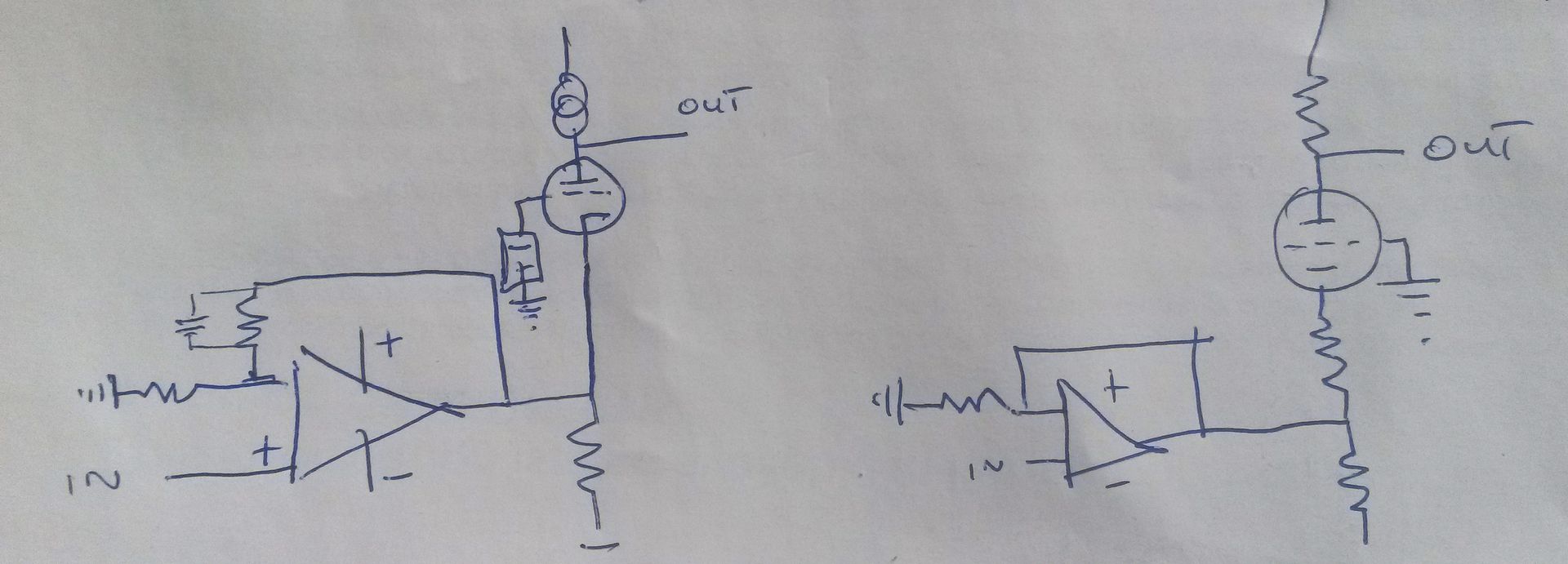
sorry bad drawing and bad picture.
Voltage devider from +12v to -12v opamp load from -12v to out, valve cathode at out, valve grid to ground, valve cathode potential adjusted with trim pot wiper to ground inbetween two fixed resistors of voltage devider.
Large value to limit current flow.
Doesn't need any bypasses does it?
#7
Posted: Sun Jun 15, 2014 1:16 pm
by Paul Barker
I've never studied opamps so forgive me if my knowledge is incorrect.
I looked at what they call the simplified schematic and I can't see any dc blocking capacitors. Therefore the problem with levellinging the opamp to a bias position at the output is that I would have to provide dc protection on the input. It might be used in a a situation where dc protection isn't required. Like an input transformer. But I don't really want to limit it's flexibility.
So I 'll probably go with CCS anode load on the valve bias the valve outside of the opamp (either cathode resistor or fixed) and use a trim pot for the opamp load which I will adjust to centre the opamp between it's +/- rails. I might figure out a visual readout to confirm it's centrality. If I could figure out how to use a magic eye for this I would be extatic.
#8
Posted: Sun Jun 15, 2014 1:45 pm
by Mike H
Your op-amp needs a negative feedback resistor divider to the '"' input else output will just be stuck at max. plus or minus, like a comparator.
Also '+' input will need to be biased to 0V, if you want the output to also be 0V. This further implies that the NFB divider needs be AC coupled to 0V only, assuming you don't want it to amplify any DC.
#9
Posted: Sun Jun 15, 2014 2:12 pm
by Paul Barker
Mike H wrote:Your op-amp needs a negative feedback resistor divider to the '"' input else output will just be stuck at max. plus or minus, like a comparator.
Also '+' input will need to be biased to 0V, if you want the output to also be 0V. This further implies that the NFB divider needs be AC coupled to 0V only, assuming you don't want it to amplify any DC.
Yes I put the feedback in the first diagram, just simplified to the DC details in later diagrams. Lazy, that's all.
But I get that you confirmed the + in and -feedback have to be at ground.
Thank you Mike.
#10
Posted: Mon Jun 16, 2014 7:50 am
by Nick
But I get that you confirmed the + in and -feedback have to be at ground.
Thats not strictly true, the op amp will regard whatever voltage the -ve feedback point is at as ground, no matter what voltage is on there.
What current do you want through the valve and what bias do you want it to run with?
#11
Posted: Mon Jun 16, 2014 8:51 am
by Paul Barker
3mA which is constrained by the current I can generate with the garden lights. On experiment 6.7mA doesn't stress them so I thought two valve stages at 3mA each. HT I attain with the solar HT so bias will depend on that, probably less than 1 volt.
(gg followed by CF, rather than gg mu follower, because of the HT the mufollower consumes, solid state CCS doesn't need the headroom, the signal level doesn't need the headroom. So I can work with 10v headroom above the GG anode)
#12
Posted: Tue Jun 17, 2014 8:08 pm
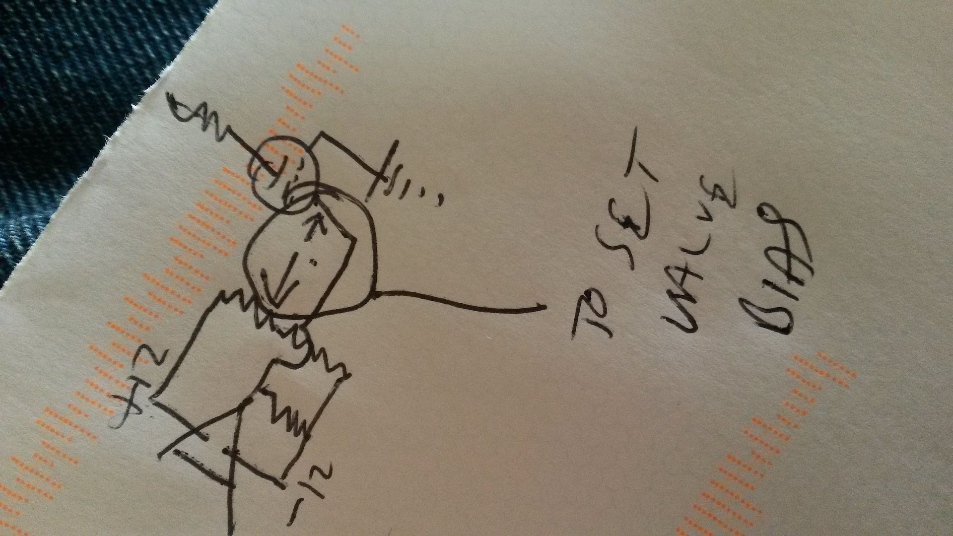
by Nick
This is what I was thinking of, but I don;t think it does anything worth having.
#13
Posted: Wed Jun 18, 2014 1:33 pm
by Mike H
Unless it provided additional gain.
Might be worth considering for MM cartridge input maybe?