#1 Utilising the high voltage linear rgeulators
Posted: Sun Dec 02, 2012 9:08 am
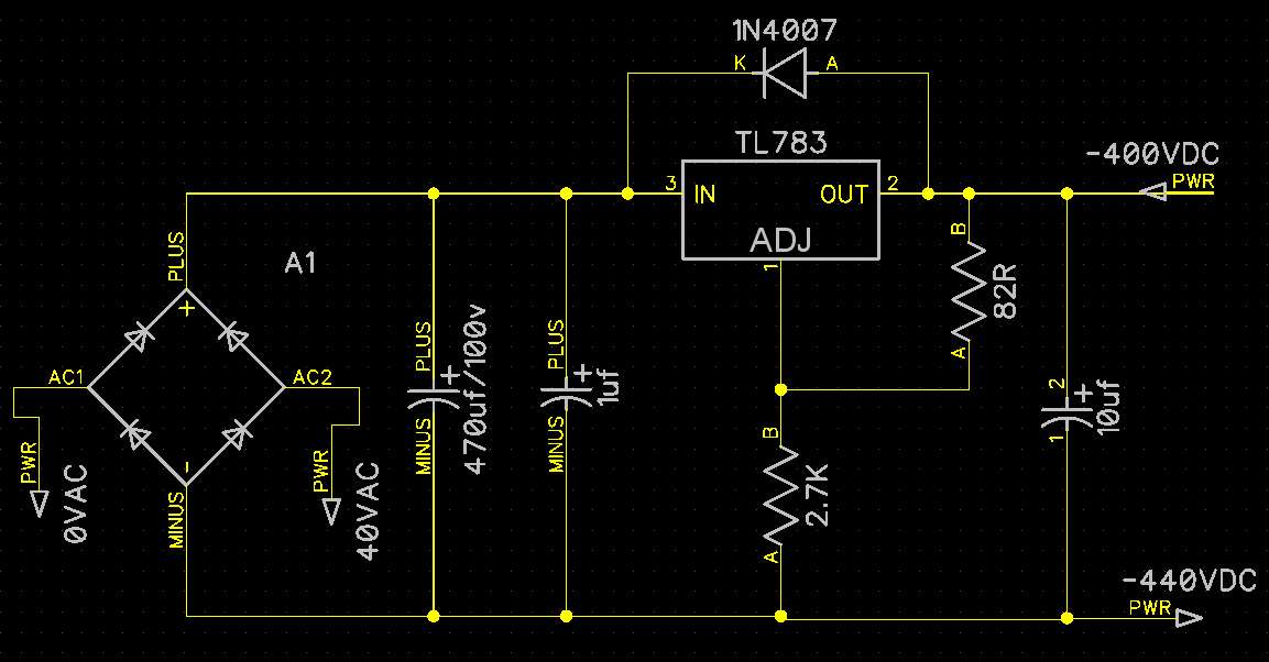
Thinking to use above topology straight off the rectifier. (inserted section learned from the 15mA situation) I see that I would have to change R1 and R2, with R1 at 82ohm for the 15mA and R2 sets up the voltage drop across the tracking preregulator, so I can share some more of the HT across it, and I shall try to set both regulators to 65v quiescent as if line was 240v, then between them they can handle any eventuality, I suppose a double gang pot which in one useage adjusts both chips is ideal but tricky to achieve. Am I making life too difficult?shall I shove a zenner from out of chip two to adj of chip 1?) Thought one of my Black Gates would assist, so put 100uF from rectifier then onto a floating version of above, using the TL783.
I was endered by it because it has a dmos output transistor within it capable of sourcing 700mA but can also handle 125v. I believe it also contains internally the diode from out to in which protects from reverse spikes. (I think I am wrong about this other people seem to add an external diode.) though in the block diagram of the chip is has inetrnal protection block, this diode may not be in it.
I took the 30ms graph (max time they give) of current /voltage tolerance
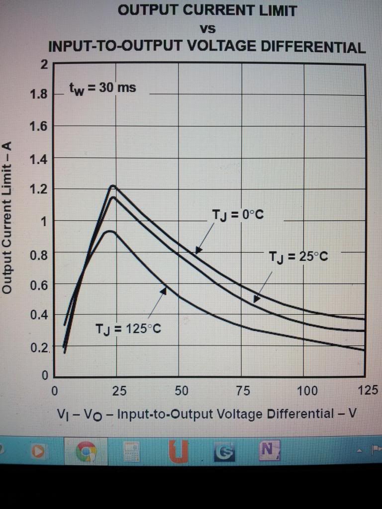
I presume using a decent heatsink a quiescent current and voltage of the 125 degree line perhaps with a 20% conservative fall back for transients would work? I mean if it isn't capable of that it will just act as a fuse and blow, then I have no B+, and aslong as Black Gate rated sufficiently no other losses but the chip.
So I could pass 100v at 180mA through the second one of these utilised in first schematic topology. I don't think the prior tracking chip shares anything but it's dropout voltage, is that right? So if I wanted to drop more voltage I would have to cascade second stages. OR I could just use our trasitional methods.
Now these will be floating so I plan to assemble then on mini boards stand them above the top plate and cover them with a cage made of the little stationary slotted steel pen holders and such like from Wilkinsons.
Question? How to you float the Adj pin? A Zenner string from true ground?OR large value R1?
OK I now found this schematic. So it seems there isn't an internal diode I better use one. And they use a large resistor for R1. I presume selected for a current. Can someone remind me the desired current for a linear reg adj pin is it 10mA? I see they have sized theirs below for 15mA. right now I read it in the data sheet, when passing 125v across the chip you have to use 15mA minimum on adj to out. So R2 would be notionally 82 ohm in their example. ADJ reference voltage would settle at a figure between 1.2 and 1.3v.
I suppose the wise money consumes most of the stand off ground voltage either with zenners or with a large value resistor, then a variable resistor right at the top, but the 82ohm R2 is fixed. So your desired output voltage can be tuned in. I can see that taking into account line variation of say 230 to 250v I would have to settle the chip at say 65v for a line of 240v so that it will maintain my desired B+ whichever persons house I plug the amp in to. Then If I want further regulation, which I may have room for, I can pop another one in as a current source and design the current for the quiescent voltage of my output valves plus the same amount again through my shunt reg valves. But if I can't fit shunt reg valves with heater supply into this baby I shall just use another series reg, not so much for the regulation, though that would maybe improve on what is already good, but as a voltage drop vehicle.