Page 4 of 8
#46 6AS7 Headphone amp
Posted: Wed Sep 19, 2007 11:56 am
by colin.hepburn
Hi All
As I have decided to re visit this headphone schematic can anyone help me out here?
As my maths is not good by first checking the circuits OK
And what I want to do is change R1.C1.R2.C2 as they are shared by both channels I don’t want to share components over both the channels can anyone give me the right value for R1/R2 for each separate channel
Thanks
Colin
#47
Posted: Wed Sep 19, 2007 12:03 pm
by Nick
Leave the caps the same, double the resistor value to 2k
Ok, youi could half the cap value, but I would be tempted not to bother.
#48
Posted: Wed Sep 19, 2007 12:11 pm
by colin.hepburn
Thanks nick
So double R1 to 2K and keep R2 @22K caps are 220uf
#49
Posted: Wed Sep 19, 2007 12:18 pm
by Nick
Thats what I would do.
#50
Posted: Sun Sep 23, 2007 3:02 am
by Mo
Pardon my ignorance gentlemen, is it not possible to run headphones with something like a 45 amp, i'm just curious because i'm seriously thinking about going down the headphone route because i'm tired of trying to get the right loudspeakers with valve amps. I'm interested in a pair of Stax electrostatic headphones.
#51
Posted: Sun Sep 23, 2007 10:47 pm
by colin.hepburn
Hi all
Well I’ve started to source part for this new headphone amp and checking the schematic I have notested that it’s drawing 90mA on each side of the 6as7 if I have got the maths right? With the 2.2k cathode resistor 200 /0.09mA = 2.2k with the ecc88 total 190mA see post 62 I think so looking for mains TX ask Jan has one 200VA 2 *270volts 200mA so thinking about ordering it assuming I have got this right if anyone can verify this and if I can ask for the maths formula with the answers pleas this would help me try to get to grippes with the maths if I can see the formula laid out
For the amp and psu
#52
Posted: Sun Sep 23, 2007 11:28 pm
by Nick
With the 2.2k cathode resistor 200 /0.09mA = 2.2k
Hang on, are you saying the voltage on the 2k2 resistor is 200v?
If it is, then the 160v elect cap is going to be unhappy.
BTW, your use of ohm is correct, if the voltage on the resistor is 200v.
EDIT:
Ah, looking att he circuit, I may see the problem. There is 200v on B+, so the anode of the value is a 200v, but the valve needs/will voltage across it, so, maybe its running with 100v across it, so the cathode will be at 100v, so the 2k2 (and the valve, and the supply) will be passing 100/2k2 = 45ma. In which case, the total currenr will be happly under 200ma. So the TX you mention should be fine.
Another EDIT:
I wonder is that transformer 240-0-240 might be a bit high, are you thinking of cap input? Maybe it should be ok with that. Yes, thinking, 240 * 0.9 = 216, lowish DCR chokes, then you should get to 200 ok, if a bit low (more DRC in the chokes) you can pad it up with a first cap.
#53
Posted: Sun Sep 23, 2007 11:56 pm
by colin.hepburn
Sorry nick
Meant to say 200b+ on the anode TX is 270-0- 270 one or two 10 H @82ohme
http://fragjanzuerst.de/eindex.htm TX TRA 400
#54
Posted: Sun Sep 23, 2007 11:59 pm
by Nick
That TX should be fine.
#55
Posted: Tue Oct 09, 2007 10:31 pm
by colin.hepburn
Hi All
I have two sets of heater supply’s on my TX one 6.3 @2A and one 6.3 @ 7A what is the best method for this valves are 1x E88CC 1x6AS7 should I use the 2amp for the E88cc or the 7amp for both valves
#56
Posted: Tue Oct 09, 2007 11:07 pm
by Nick
I would do as you suggest, 2A for ECC 7A for 6as7, then you can elevate the heaters individually.
#57 12B4A HD Headphone Amp upgrade
Posted: Thu Nov 29, 2007 6:18 pm
by colin.hepburn
Hi All
I am upgrading my 12B4a Headphone Amp to a higher current version going with the updated Schematic upping the current from 30mA to 42mA but require some help with the PSU I have two options due to parts I have
Opt one
TX 250/260v 100mA SS Rec C1 150uf choke3H/100 ohms C2 150uf C3 22uf 42mA
Opt two
270-0-270v 100mA valve rec EZ 81 C1 50uf Choke 3H/100ohms C2 150uf C3 150uf C4 22uf 42mA
Problem is cant get good results in Duncan’s PSU II Plus can anyone verify the correct B+ voltage at last Cap 262 volts 100K for 131volts at anode of V1
Thanks all advice Appreciated
#58
Posted: Tue May 20, 2008 6:40 pm
by peranders
One of my headphone amps of my own design look like this
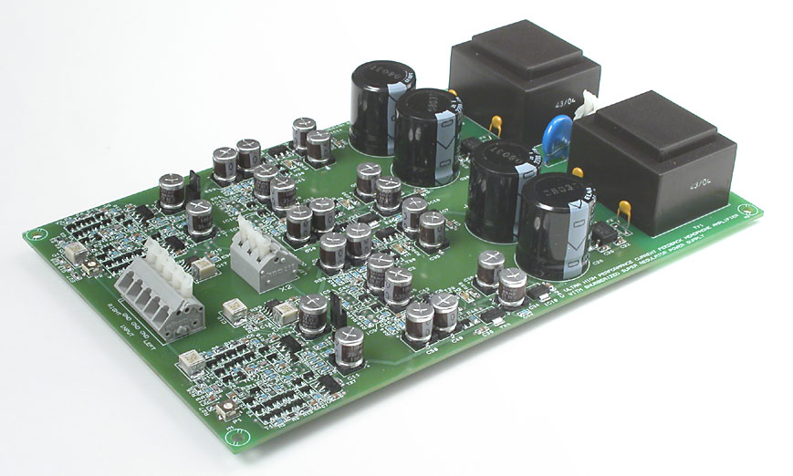
The power supply consists of four super regulators and the whole design is dual mono.
Distortion figures here:
http://www.jmd.szm.sk/Audio/Measurement ... F_amp.html
#59
Posted: Fri Jul 25, 2008 5:40 am
by colin.hepburn
Hi All
Got problem with headphone amp volume at switch on after warm up some times I get full volume in right ear with vol at zero but incressing the vol will balance out the levels to the norm not good for can senn s HD650s some times a wiggle of the pot will fix it but not every times the pot is a alps 100k assuming pot is dirty or on way out what do you think pleas check schematic can anyone help on this
Cheers

Colin
#60
Posted: Fri Jul 25, 2008 8:14 am
by Nick
My money is on the Pot, but I would add a 100k grid leak between the virst valve grid and ground. And it might help a little.