DTBs 6B4G
#121
I was thinking more like you're left and right feet didn't know which step was who's?

-
Dave the bass

- Amstrad Tower of Power
- Posts: 12276
- Joined: Tue May 22, 2007 4:36 pm
- Location: NW Kent, Darn Sarf innit.
#122
Got home from Hols and found that that lovely chap that is named Will has sent me some lovely clamping diodes to stop my 6EM7's and 6C4C's from arcing on power up.
Hat's off to Will, many thanks sir, much obliged.
I'm back to work next week and will get back to building stuff asap.
DTB
Hat's off to Will, many thanks sir, much obliged.
I'm back to work next week and will get back to building stuff asap.
DTB
"The fat bourgeois and his doppelganger"
-
Dave the bass
- Amstrad Tower of Power
- Posts: 12276
- Joined: Tue May 22, 2007 4:36 pm
- Location: NW Kent, Darn Sarf innit.
#123
Just double checking here Gents,
On a C3g valve, it's a pentode right. There's 3 grids, I think from in the direction from Anode to cathode they're called Suppressor grid, screen grid and finally the signal grid closest to the Cathode.
Have I got that right?
I ask 'cos I need to connect the Cathode direct to the suppressor grid in DHTskis cct and I want to make sure I'm connecting the right pins together. The info I've got is all in Germanish.
Ta chucks,
DTB
EDIT, yes. I think I got that right Netterweb is handy innit.
On a C3g valve, it's a pentode right. There's 3 grids, I think from in the direction from Anode to cathode they're called Suppressor grid, screen grid and finally the signal grid closest to the Cathode.
Have I got that right?
I ask 'cos I need to connect the Cathode direct to the suppressor grid in DHTskis cct and I want to make sure I'm connecting the right pins together. The info I've got is all in Germanish.
Ta chucks,
DTB
EDIT, yes. I think I got that right
"The fat bourgeois and his doppelganger"
-
Dave the bass
- Amstrad Tower of Power
- Posts: 12276
- Joined: Tue May 22, 2007 4:36 pm
- Location: NW Kent, Darn Sarf innit.
#124
And another question...
I know you're all gonna point and laff at this one but this is my first DHT build so bear with me... I've got a separate 6.3V DC feed to the filament of each 6B4G, on Nicks cct diagram one end of the filament/Cathode is unconnected so I guess thats where I stick the +6.3V DC feed but where does the side of that feed go?

On the other end of the filament or the 0V rail on the amp?
Sorry but I'm a bit confoozed (and its a Monday).
DTB
I know you're all gonna point and laff at this one but this is my first DHT build so bear with me... I've got a separate 6.3V DC feed to the filament of each 6B4G, on Nicks cct diagram one end of the filament/Cathode is unconnected so I guess thats where I stick the +6.3V DC feed but where does the side of that feed go?
On the other end of the filament or the 0V rail on the amp?
Sorry but I'm a bit confoozed (and its a Monday).
DTB
"The fat bourgeois and his doppelganger"
#125
The fillament supply is connected across the two fillament pins, the connection to the cathode resistor and cap, is from one of those pins. It probably doesn't matter which, but I prefer the -ve of the two.
Whenever an honest man discovers that he's mistaken, he will either cease to be mistaken or he will cease to be honest.
-
Dave the bass
- Amstrad Tower of Power
- Posts: 12276
- Joined: Tue May 22, 2007 4:36 pm
- Location: NW Kent, Darn Sarf innit.
#126
Many thanks Nick, DHTski's coming on well. Not as tidy as normal but its a bit more involved this time.
TTFN
DTB
TTFN
DTB
"The fat bourgeois and his doppelganger"
-
Dave the bass
- Amstrad Tower of Power
- Posts: 12276
- Joined: Tue May 22, 2007 4:36 pm
- Location: NW Kent, Darn Sarf innit.
#128
Yes, I remember you and Simon recommended that when he built his version.Nick wrote:Remember to keep the c3g gridstoppers near the sockets.
I've got the 150ohm and 100K right up close, I'm not tag stripping anything. Its' all hanging off the socket bases.
DTB
"The fat bourgeois and his doppelganger"
-
Dave the bass
- Amstrad Tower of Power
- Posts: 12276
- Joined: Tue May 22, 2007 4:36 pm
- Location: NW Kent, Darn Sarf innit.
#130
Many thanks Andrew, I noticed there was 2 connections to the Cathode, Is it wise (good practise?) to connect both ends to the the 68R? I confess I've only taken one end so far, the other is left NC.Andrew wrote:Hi Dave,
On the C3g
Connect
2 & 7 to the cathode above the 68R
3 is the anode
6 grid (this is the grid on the triode)
4 to the voltage ref
1 & 8 heaters
cheers,
-- Andrew
DTB
"The fat bourgeois and his doppelganger"
-
simon
- Thermionic Monk Status
- Posts: 5643
- Joined: Thu May 24, 2007 11:22 am
- Location: People's Republic of South Yorkshire
#131
Looks like you might be ready for Witham Dave? I'm hoping to get be able to make it for a weekend of beer and hi fi - I could bring my 2A3 version to compare perhaps? I'll even bring my bestest RCAs, sadly only dualplates. I saw some nice looking monoplates on ebay t'other day, but at 600 dollars I didn't bid...
Simon.
Simon.
-
Dave the bass
- Amstrad Tower of Power
- Posts: 12276
- Joined: Tue May 22, 2007 4:36 pm
- Location: NW Kent, Darn Sarf innit.
#132
Yeah, hope so Simon.
That'd be good comparing projects, I was going down the 2A3 route but then NickG wisley steered me towards 6B4G as I already had an HT TX for it, wise.
This morning Komrade DHTski looked like this...
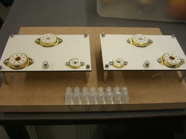
Tonight he has almost all the components on one channel fitted. I was on my own in the workshop today and my plans to do lots of work on him fell through Lunchtime tommorrow should see a bit more done hopefully.
How's yours sounding Simon, did you get the instability sorted in the end?
Look forward to seeing you at WF, I'll be there Friday night and all day saturday but need to make tracks early evening.
DTB
That'd be good comparing projects, I was going down the 2A3 route but then NickG wisley steered me towards 6B4G as I already had an HT TX for it, wise.
This morning Komrade DHTski looked like this...
Tonight he has almost all the components on one channel fitted. I was on my own in the workshop today and my plans to do lots of work on him fell through
How's yours sounding Simon, did you get the instability sorted in the end?
Look forward to seeing you at WF, I'll be there Friday night and all day saturday but need to make tracks early evening.
DTB
"The fat bourgeois and his doppelganger"
-
Dave the bass
- Amstrad Tower of Power
- Posts: 12276
- Joined: Tue May 22, 2007 4:36 pm
- Location: NW Kent, Darn Sarf innit.
#134
Will do Andrew, I measured betwixt pins 2 and 7 and they were internally connected.Andrew wrote:I would personally connect 2, 7 and 5 together and thence to the 68R which goes to ground. I certainly used both cathode pins 2 & 7 on the C3g I use as a driver in the tx-coupled Aikido.
cheers,
-- Andrew
Then I looked at the Data sheet...duh, they would be wouldn't they
Cheers for the advice everyone as always. Lordy knows I need it.
DTB
"The fat bourgeois and his doppelganger"
-
simon
- Thermionic Monk Status
- Posts: 5643
- Joined: Thu May 24, 2007 11:22 am
- Location: People's Republic of South Yorkshire
#135
Dr Nick got the instability sorted out - lack of gridstoppers on the C3g.Dave the bass wrote:How's yours sounding Simon, did you get the instability sorted in the end?
It sounds pretty good, it's really fast, and plays tunes in the bass, but doesn't have as much detail as the KRs perhaps. To be honest it's not being used at the moment, no opportunity or space which is a shame really.
I hope farting isn't mandatory at Witham