Next Single Ended build

What people are working on at the moment
User avatar
Paul Barker
Social Sevices have been notified
Posts: 8991
Joined: Mon May 21, 2007 9:42 pm

#1 Next Single Ended build

Post by Paul Barker »

Cressy has come up trumps with yet another skilfully made case.

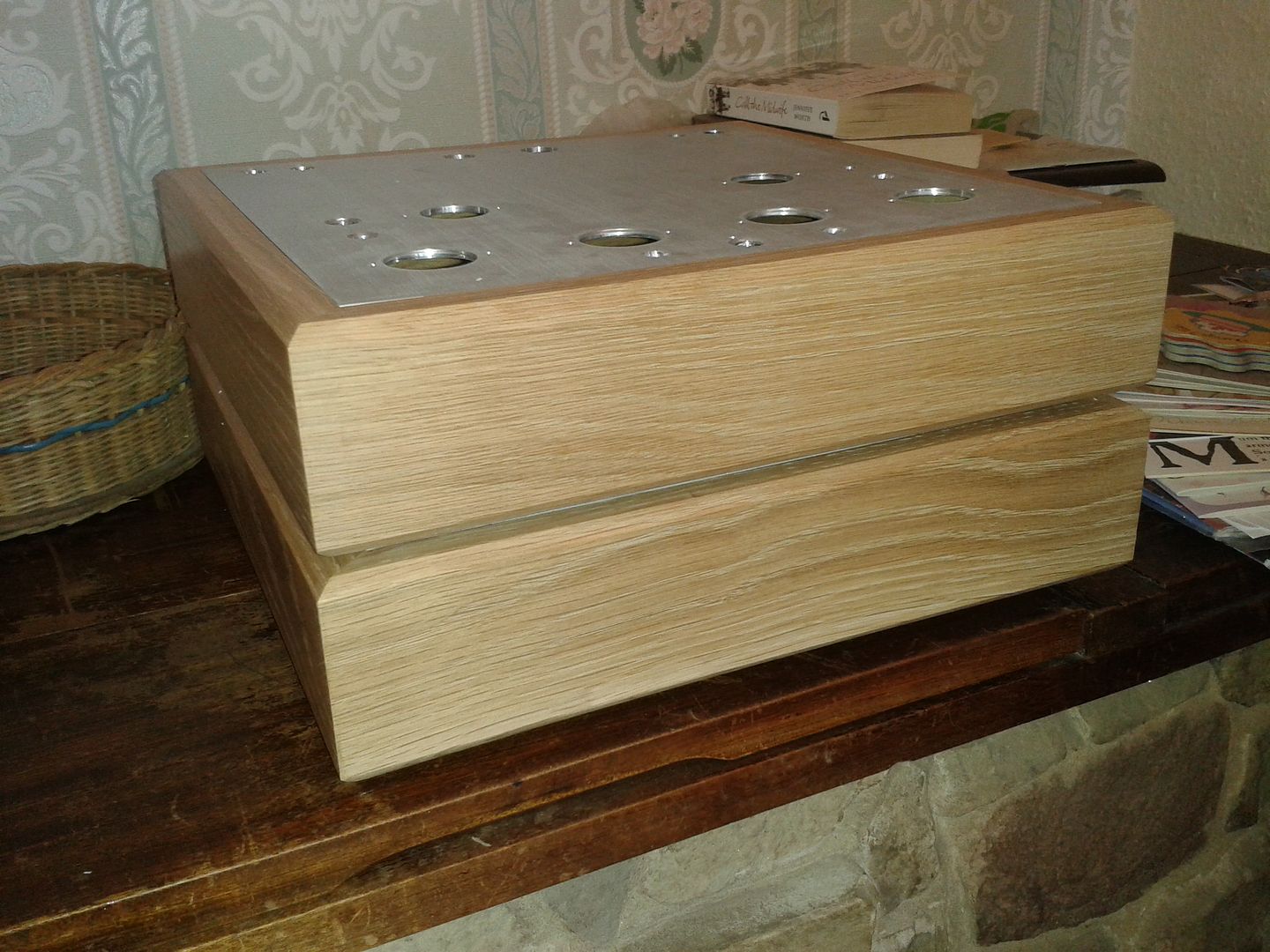
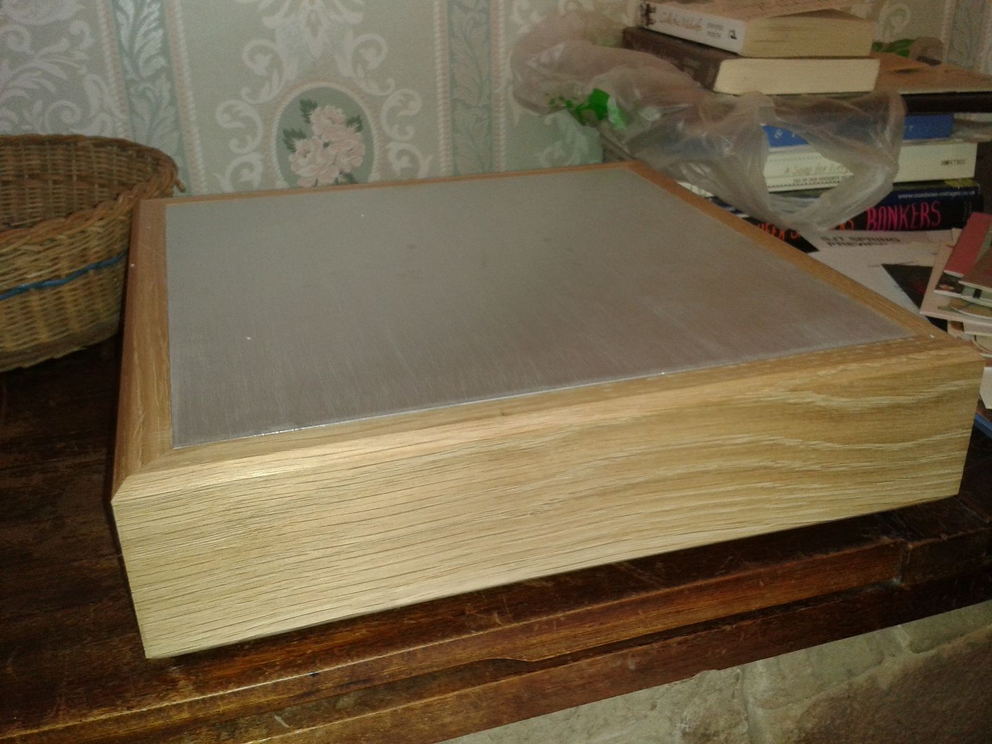
I supplied the poor condition aluminium sheet and he has made wooden cases to fit like a glove. I don't know how he does it.

the one I have punched before I sent it to him is for the amplifier the blank one is the power supply.

Image

Image

Image

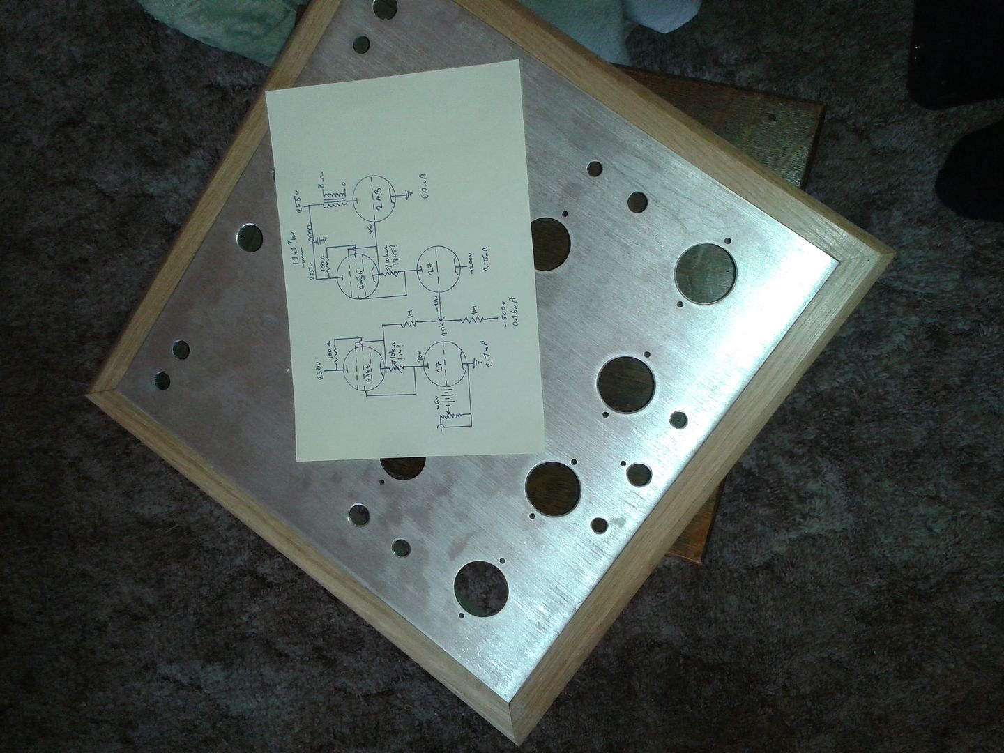
The eagle eyed will have zoomed in on the rough schematic so I had better give a brief talk through.

I wanted to not use any capacitors in the amplifier part. The power supply could go capacitorless eventually but that had better start with capacitors or it will never get built.

For direct coupling the diy community normally builds "free lunch" "DRD" or "Monkey" clones or adaptations.

all of those have the cathode resistor which needs a bypass. I last direct coupled with VR tubes in place of those resistor capacitor combinations. I think the vr tube cloning sounded pretty dam fine, but as has been pointed out by others vr tubes are not without distortion. Though to my ears they sound better than capacitors, there are other ways.

what we are doing ultimately is level shifting.

The other way to level shift with VR tubes is to pull some current to light the vr tube and place it between the two valves where the capacitor would otherwise go. The level designed is quite certain within the variance of the vr tubes which can be discovered on a test rig. Certainly for a single stage this is a valid solution. But we still have the vR tube in the signal path.

So I decided to try the very old technique of a resistor devider. Not at all efficient, but you are swapping your capacitor for resistors. Once perfect devision is arrived at on test two 1/2 watt Tantallum resistors could be inserted, and now your coupling mechanism is highest quality available. Compared to copper foil silver wired caps much cheaper, and probably sound better anyway.

More soon, Azda deliver just arrived. :shock:
"Two things are infinite, the universe and human stupidity, and I am not yet completely sure about the universe." – Albert Einstein
User avatar
Paul Barker
Social Sevices have been notified
Posts: 8991
Joined: Mon May 21, 2007 9:42 pm

#2

Post by Paul Barker »

So the first DC stage is level shifted with two tantalum resistors ultimately.

Likewise ultimately the current which the 6AK6's set for the 27 to operate within can also be decided finally by fixed Tantallum's.

The hard part are the various power supply's.

Main B+ 255v is the only one which has a power demand upon it. That will be an average quality choke input supply with Black Gate caps, because I have enough to do without making three capacitorless power supplies. Those will have to follow.

I had a brainwave one morning just out of the blue that the low current of the 27 that drives the 2a3 (mine will probably be 6b4g's but could have equally been 2a3's or PX4's) So due to it's low current it could simply have it's own negative supply. No need to make a main power supply which is + 255v and - 255v. Uses less transformer power to make a separate -200v that only has to provide for 8mA or so. this could be voltage multiplied then shunt regulated for example from almost any small scrap transformer you have lying around. Because it doesn't need a lot of current shunt regulation is an obvious choice.

So having decided on that method for the key DC stage. Decisions decisions. Do I dc couple the first stage. To avoid a capacitor I cannot use the same approach, because the 27 here has to interface with the outside world. It needs to be grounded either at the grid or the cathode or I have to use a cap on the input, and my compromise has crept in. So it is level shifted to the outside world with fixed bias batteries. Many other ways to work here. Input transformer gives good possibilities but they can't tolerate very much dc potential so you can't go mad here. Good ones cost plenty of money. This design is intended to save money. Why waste money, even if you have it. Think of those who might follow. We can all build great amps with Tamura transformers and silver or copper foil caps coupling for us.

We loose more than 50% of the gain stage 1 to 2 but nothing stage 2 to output.

We have therefore decided to maximise the load on the 27's (to the extent we can without using caps or solid state) so the A (amplification) is close to the mu. But I fell deliberately short of the whole Kimmel mufollower, as it contains a capacitor.

Because this only has to drive a 2a3 type valve I have chosen not to go the route of high transconductance.

When you see the 833a adaptation of this it will have something like the d3a involved and a high current CF direct drive to the output valve, level shifted all the way.

There is sufficient amplification left after the resistor devider to give full power from 1v RMS with headroom. The two 27 stages, assuming the pentode gives 200k of resistance to them have a pretty good loadline, so they should be without significant distortion. any slight differences in their characteristic curves to direct heated alternatives should go unnoticed with 200k loadline.

the mu output's don't go through any capacitors so I can't see anything but advantage to using that option. But I might try output at anode of 27 to ensure the assumption is right. Might find first stage anode out second stage mu out for example, sounds best. Who's to know?

The negative supply on the resistor devider is high voltage but extremely low current. So as before voltage multiplier and shunt regulator. I could build just the -500v one and pick off the -200v along the multiplier. Shunt regulate both.

No -3db bass corners to worry about until the audio arrives at the output transformers.
"Two things are infinite, the universe and human stupidity, and I am not yet completely sure about the universe." – Albert Einstein
User avatar
Paul Barker
Social Sevices have been notified
Posts: 8991
Joined: Mon May 21, 2007 9:42 pm

#3

Post by Paul Barker »

there is too much voltage that has to be consumed on stage two for the 6ak6 to tolerate hence the 13k odd resistor (Tant of course) which would be added to the load rather than decoupled. Might aswell add a little extra load.

I could put Alex feedback in there but don't have much amplification headroom so will just go conventional for the time being.

I did think of using the 5687 for the second stage, which would have given me loads of headroom and loads of drive, I could then use single stage feedback and I could also modify the design for the GK71 GM70 300b etc. But I don't need to, so for the 2a3 it is and stick to low powered stages.

When I need power I can make power. Right now I don't need power, I am after subtle quality not a sledge hammer.
"Two things are infinite, the universe and human stupidity, and I am not yet completely sure about the universe." – Albert Einstein
User avatar
IslandPink
Amstrad Tower of Power
Posts: 10041
Joined: Tue May 29, 2007 7:01 pm
Location: Denbigh, N.Wales

#4

Post by IslandPink »

So are those basically mu-follower stages then ?
Looks very interesting .
Lack of unecessary bass -3dB points is a very good thing. That's one reaon I like the 4P1L with no cathode by-pass and a VR tube on G2 . However, not as much gain for all applications ..
"Once you find out ... the Circumstances ; then you can go out"
User avatar
Cressy Snr
Amstrad Tower of Power
Posts: 10582
Joined: Wed May 30, 2007 12:25 am
Location: South Yorks.

#5

Post by Cressy Snr »

Interesting concepts in there Paul.
Sgt. Baker started talkin’ with a Bullhorn in his hand.
User avatar
Paul Barker
Social Sevices have been notified
Posts: 8991
Joined: Mon May 21, 2007 9:42 pm

#6

Post by Paul Barker »

Yes Mark in stripped down form so as not to require a cap.

Steve the concepts all pre-exist, but seldom used.
"Two things are infinite, the universe and human stupidity, and I am not yet completely sure about the universe." – Albert Einstein
steve s
Shed dweller
Posts: 2844
Joined: Wed May 30, 2007 6:19 pm
Location: east yorks

#7

Post by steve s »

Paul Barker wrote: When I need power I can make power. Right now I don't need power, I am after subtle quality not a sledge hammer.
Thats a sensible route paul, after all its living room volume that is the priority...
and you could also slot a pair of your px4' s in when you get bored..

Looking foward to hearing it
The tube manual is quite like a telephone book. The number of it perfect. It is useful to make it possible to speak with a girl. But we can't see her beautiful face from the telephone number
User avatar
Paul Barker
Social Sevices have been notified
Posts: 8991
Joined: Mon May 21, 2007 9:42 pm

#8

Post by Paul Barker »

Might not be ready for Owsten but the next one. You never know.
"Two things are infinite, the universe and human stupidity, and I am not yet completely sure about the universe." – Albert Einstein
User avatar
Paul Barker
Social Sevices have been notified
Posts: 8991
Joined: Mon May 21, 2007 9:42 pm

#9

Post by Paul Barker »

OK I had to think about this. Shall I just build it for PX4 and have done with it. So I studied the data.

PX4 can be operated at 300v SE whereas 2a3 250v SE.

The OPT's I am using in this project are 4k5 into 8 ohm R Cores.

So I enlarged the characteristic curves and printed them off, to see what power output and 2nd Harmonic distortion I get out of each valve at the max voltage/dissipation.

PX4 shows 3.2 Watts with 2.5% 2nd Harmonic Distortion

Image

and the 2a3 shows 2.5 Watts at 3.33% 2nd Harmonic Distortion

Image

But if your 2a3's aren't precious to you or say they are Sovtec's which are supposedly much the same as the Sovtec 300b you could take your own risk and operate them at 300v like the PX4 to achieve 4.9 watts at 4.43% 2nd.

Image

I think 3 plus watts at 2.5% from a PX4 is perfect for my living room. So I'll break out the PX4's.

Something interesting emerged which with our ears people such as Steve Shiels and myself already knew. PX4 is less distorted than 2a3. OK I calculated this out to get the exact figures but any fool can see the pinching in the 2a3 curves relative to the PX4.

You may recall when I was curve tracing my PX4's they were along these same lines, except a couple which exceeded these distortion expectations, I mean to say even lower distortion as clear as night is from day.
"Two things are infinite, the universe and human stupidity, and I am not yet completely sure about the universe." – Albert Einstein
User avatar
Paul Barker
Social Sevices have been notified
Posts: 8991
Joined: Mon May 21, 2007 9:42 pm

#10

Post by Paul Barker »

the two 27 operating points are drawn here and show that they will give plenty of headroom along a pretty linear region.

Image

Hoping that the cascode of 27's should neutralise and the dominant distortion will be the px4's 2.5%

We'll find out when it's built and the distortion meter is presented to it. :D

the slew rates you lot bang on all the time about, I calculate the 2a3 needs 2 mA using Stephie Benches criteria of 5X for quality. The driving 27 is at 3.7mA and passed through the pentode CF output direct to the grid, so I don't think I need to strike out my D3a's or change my second stage to 5687:- YMMV. I checked the capacitance of the PX4 compared to the 2a3 and because the voltage drive is less, despight slightly higher capacitance the slew is exactly the same 2mA. The capacitance used is the miller plus grid to filament.

DC all the way, no mechanism for Bass roll off until the output transformer, no cathode resistor bypass caps. So few resistors they can all be Tantallum once exact values are found empirically. Pot's shall be used for initial build and levels shifted by that means. Initially build stages 1 to 2 and level those two exactly where I want the bias for the PX4. then couple up the PX4.

The hard part of the build is the power supplies. Those will have to be regulated as once the Tantallum resistors are in place the Level stability is entirely up to the power supplies until the valves deteriorate. Probably a digital current display of the output valve will suffice, to alert a drift. Then turn it over and make adjustments. Shouldn't happen very often. Build it, forget it, get on with life.
"Two things are infinite, the universe and human stupidity, and I am not yet completely sure about the universe." – Albert Einstein
User avatar
ed
retired
Posts: 5384
Joined: Thu Jun 21, 2007 4:01 pm
Location: yorkshire
Contact:

#11

Post by ed »

I appreciate this is your hobby Paul, and you are truly passionate with all these figures...

but I'm fascinated by the subjective objective argument as it applies here......

can you honestly hear these differences?

this is not a contentious post, and I'm not knocking your enthusiasm...I'm genuinely interested

edit: should really qualify this.....I mean by differences, 2.5% vs 3.3% and the fact that there are other harmonics in there in the first place
There's nowhere you can be that isn't where you're meant to be
User avatar
Nick
Site Admin
Posts: 15754
Joined: Sun May 06, 2007 10:20 am
Location: West Yorkshire

#12

Post by Nick »

One thing that I would check (you may well have done so) is the impedance into the second stage grid and the effect of miller on that. I assume you will be using fairly high value resistors for the divider so as not to load the first stage to much, so you may have a -3dB low pass point to check.
Whenever an honest man discovers that he's mistaken, he will either cease to be mistaken or he will cease to be honest.
User avatar
Paul Barker
Social Sevices have been notified
Posts: 8991
Joined: Mon May 21, 2007 9:42 pm

#13

Post by Paul Barker »

ed wrote:I appreciate this is your hobby Paul, and you are truly passionate with all these figures...

but I'm fascinated by the subjective objective argument as it applies here......

can you honestly hear these differences?

this is not a contentious post, and I'm not knocking your enthusiasm...I'm genuinely interested

edit: should really qualify this.....I mean by differences, 2.5% vs 3.3% and the fact that there are other harmonics in there in the first place
I haven't calculated the other harmonics because it is very time consuming to do what I have done, and it is well enough understood that in valves of this nature with designs of this topology that 2nd harmonic is the significant one to consider. Was it pentodes, A2 or push pull operation the other distortions would break through.

Yes I have with others heard very clearly the difference in sound between PX4 and 2a3. I am not saying these distortion measurements (graphically measured not tested empirically) explain that preferred sound. It may be a lot more than that, such as materials choices to name but one. I am saying though that from what I have heard subjectively the objective figures these lines portray make sense to me. That is what I am wanting to share with you.

If you forget your doubting the subjective abilities of human hearing, and only look at the objective calculations demonstrated above, which you are very welcome to print off and measure out for yourself to show you that I am not making this up, to conclude one shouldn't hear this difference would to me make no sense.
"Two things are infinite, the universe and human stupidity, and I am not yet completely sure about the universe." – Albert Einstein
User avatar
Paul Barker
Social Sevices have been notified
Posts: 8991
Joined: Mon May 21, 2007 9:42 pm

#14

Post by Paul Barker »

Nick wrote:One thing that I would check (you may well have done so) is the impedance into the second stage grid and the effect of miller on that. I assume you will be using fairly high value resistors for the divider so as not to load the first stage to much, so you may have a -3dB low pass point to check.
It has niggled me Nick, I had better calculate it right now and come back to you on that.

If it fails the alternatives are pull more current or change to series VR tubes. I was wanting to avoid the VR tubes.
"Two things are infinite, the universe and human stupidity, and I am not yet completely sure about the universe." – Albert Einstein
User avatar
Paul Barker
Social Sevices have been notified
Posts: 8991
Joined: Mon May 21, 2007 9:42 pm

#15

Post by Paul Barker »

SHugar!

Thank you for alerting me Nick. I suppose we need the corner frequency at 40khz with 30pf capacitance the series resistor needs to be 132k

OK it's not blown it out of the water. I can get another 2.2mA through the 6AK6. In any case if I were to use VR tubes I would be pulling that type of current through the VR tube (using 3mA max rated VR's) so the only downside of resistors remains the voltage devision. The advantage hopefully being better sonics than VR tubes.

Do you think -3db at 40khz is enough Nick? Or for quality do I need to take it higher? I am not sure if the phase shift of 45 degrees at 40khz will mean a slight phase shift at 20khz or whether it would be heard. Anyone have an opinion?
"Two things are infinite, the universe and human stupidity, and I am not yet completely sure about the universe." – Albert Einstein
Post Reply