It is about time I built a push pull amplifier

What people are working on at the moment
User avatar
Paul Barker
Social Sevices have been notified
Posts: 8985
Joined: Mon May 21, 2007 9:42 pm

#151

Post by Paul Barker »

Thanks James.

I have now swept it and there is a 3dB per octave LF roll off so at 80hz it is 0dB at 40hz -3db at 20 hz -7dB.

There are two positions where LF would roll off, both of them transformers. So clearly as the roll off is 3dB per octave only one transformer is behind most of the way with the other adding a small influence of 1dB down at 20hz.

At HF considering once more it passes through two budget transformers the roll off is pretty good. between 15k and 30k (one Octave) it rolls off at 5.5dB so it is likely that beyond 15k each transformer is rolling off at 3dB per octave. This would be expected. But up to 20k we are below -2dB we only cross -1dB at 18khz a frequency I am unliley to hear.

The important point is there are no nasty reonsances the roll off just increases pace until the Octave between 50khz and 100khz is 21dB. There is no point up to 100khz where it peaks or resonates. After 100khz where we are down 34dB the signal is too small relative with noise to carry on.

We aren't trying to make a radio frequency amplifier after all. It's good that we haven't. :shock:

Test performed at 1 Watt.

Image
"Two things are infinite, the universe and human stupidity, and I am not yet completely sure about the universe." – Albert Einstein
User avatar
Paul Barker
Social Sevices have been notified
Posts: 8985
Joined: Mon May 21, 2007 9:42 pm

#152

Post by Paul Barker »

The roll off at HF does have a slight hump at 55kHz. Well you would expect a hump, this doesn't look very pronounced.

Image
"Two things are infinite, the universe and human stupidity, and I am not yet completely sure about the universe." – Albert Einstein
User avatar
Paul Barker
Social Sevices have been notified
Posts: 8985
Joined: Mon May 21, 2007 9:42 pm

#153

Post by Paul Barker »

As the inductance bridge is at the lockup you shall have to wait to find out which transformer is responsible for -3dB at 40hz.

If it is the output, simples, switch valves for lower anode impedance like 2a3 and use 4 ohm speakers (if I had any) on 8 ohm tap for 4k load. Just get another transformer otherwise, or use a sub.

If it is interstage, change 6em7 Sec II for 6as7. Simples
:D
"Two things are infinite, the universe and human stupidity, and I am not yet completely sure about the universe." – Albert Einstein
User avatar
Paul Barker
Social Sevices have been notified
Posts: 8985
Joined: Mon May 21, 2007 9:42 pm

#154

Post by Paul Barker »

You want me to repeat the test measuring at the output of the interstage don't you :?: Go on admit it :!:

OK I did it.

A rather unbelievable and spectacular result is that the Interstage connected as per most recent diagram with 6em7 is flat down to 10hz below which I cannot measure.

So the -3dB per Octave experienced with -3dB point at 40hz is entirely because of the output transformers.

Mike is going to love this because the interstages come from him, the outputs come from a girl who winds her own for the guitar amp boys.

OK for leed guitar!
"Two things are infinite, the universe and human stupidity, and I am not yet completely sure about the universe." – Albert Einstein
User avatar
Paul Barker
Social Sevices have been notified
Posts: 8985
Joined: Mon May 21, 2007 9:42 pm

#155

Post by Paul Barker »

Now for a bass response work back.

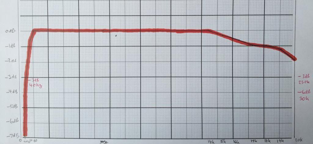
We know that we are -1dB at 64hz

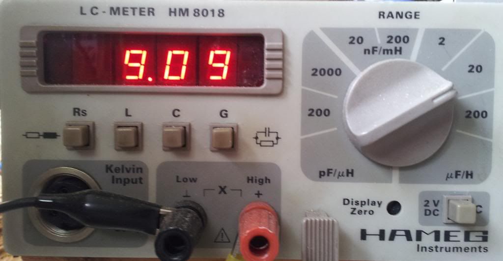
We now also know that the Plate to Plate inductance of the transformer is 9.09 Henry.
Image
With the slight proviso this was measured statically and low frequency inductance rises with signal level. However Fritz says that it is best to calculate required primary inductance RL at static inductance then things are best for worst case scenario.

What we have to work out is the Rp becuse we have no idea what it is. Triode data is not available.

We can estimate Rp by working back the inductance formula puting in all the known factors and arrive at the only Rp which fits.

wLo=2RA

RA = (2 X Rp) parallel with RL (which we know to be 8k)

w is 2pif which to us is 402 because we know f is 64.

We know L to be 9.09

So RA = 9.09 X 402 = 3,654.

Now RA is made up of the formula (2RpX8000)/(2RP+8000)

So because my mathematic ability stops here I put the figure for RA into a spreadsheet and tried a column of Rp values in the above formula until I got a match. If someone can break down the algebra please do?

My figure is 3,364 ohms anode impedance.

So now that we know that figure we can work out the required inductance for our desired -1dB frequency.

2RA = 2 X 3,654 = 7,308

Inductance = 7308/2pif

For 20hz the figure is 125h for 40hz it is 29h. If you wish to improve quality and calculate it for 0.5db multiply the result by 1.9 and Fritz advises this figure because the phase angle improves to 15 degrees which he says this "appears to be a reasonable value for good fidelity".

Therefore for hi fidelity at 20hz we need Primary inductance of 237h or at 40hz 55h.

Now I would be perfectly happy with 40hz.

So working back where does that put us with this amplifier? Where is the hi fidelity bass response? Well without more workings out, if we round up the 1.9 to 2, we simply double the frequency.

So we have hifi down to 128hz.

Or to put it another way, these transformers are a pile of pooh.

The real problem is that they have wound them for 8k. If they had wound them for 4k they could be used for a 2a3 for instance, though they would still be of poor quality for push pull transformers. Budget Se transformers which have to be gapped are quite often only 10h and seldom greater than 20h. But push pull transformers have no excuses for such shoddy quality.

They shall have to go on eBay as guitar amplifier transformers. OR else I shall have to make a couple of guitar amplifiers and bang those on eBay. One or the other.

You can still get to hear the amp at Owsten.

I now understand more clearly why my little 6em7 750mW amp stomps all over it at low level!

If they had wound them as 3k for 2a3 they would be -1db at 18 hz and good phase response at 36hz which would be spectacular preformance.

Or at 8k they would be 23hz 46hz but how much power would 2a3's produce into 8k?

Maybe I need to find out? I shall have to be careful I can see this journey culminating at my nemesis.
"Two things are infinite, the universe and human stupidity, and I am not yet completely sure about the universe." – Albert Einstein
User avatar
IslandPink
Amstrad Tower of Power
Posts: 10041
Joined: Tue May 29, 2007 7:01 pm
Location: Denbigh, N.Wales

#156

Post by IslandPink »

I wondered why the bass wasn't so good, but with a P-P inductance of 9H, I can understand . Do you have any option to get something better in there ? One of the advantages of PP as I see it is that you can get the output trannie inductance high enough to get good performance into the sub-10Hz region, and that has big effects on the bass tone and bass timing even at 50Hz or more.
"Once you find out ... the Circumstances ; then you can go out"
User avatar
Paul Barker
Social Sevices have been notified
Posts: 8985
Joined: Mon May 21, 2007 9:42 pm

#157

Post by Paul Barker »

IslandPink wrote: Do you have any option to get something better in there ?
I do have that pair of Bud's no 1's out there on loan, which you sourced.
IslandPink wrote: One of the advantages of PP as I see it is that you can get the output trannie inductance high enough to get good performance into the sub-10Hz region, and that has big effects on the bass tone and bass timing even at 50Hz or more.
Which is what has upset me most about this experience. There are really no excuses for making an 8k PP transformer with such poor LF performance. Unless of course you only intended them for leed guitar, which might be the case here. There are other elements which show me attention to detail was lacking, the bolts used were so shoddy it was as if the transformers were made in a Chinese sweat shop. Anyone in the West who genuinely hand wound these at home would have sent them out with better screws. They were so poor I binned them so can't show you. they have much more the feel of a product made by someone on 50p an hour who had no concept of what they were for.
"Two things are infinite, the universe and human stupidity, and I am not yet completely sure about the universe." – Albert Einstein
User avatar
Paul Barker
Social Sevices have been notified
Posts: 8985
Joined: Mon May 21, 2007 9:42 pm

#158

Post by Paul Barker »

a bit slow to catch on I just realised the WAD Tim de Paravicini 300b PP also employs a feedback winding on the IT but he feeds it back to the beginning. I think I need it where it is, to reduce the impedance of the driver. Plus I don't want to cancel the 2nd harmonic of the VA as it is required for timbre.

Tim doesn't let on to the scale of his feedback winding, I imagine mine is greater. Works great anyway. Done deal.
"Two things are infinite, the universe and human stupidity, and I am not yet completely sure about the universe." – Albert Einstein
Neal
Shed dweller
Posts: 2300
Joined: Fri Aug 03, 2007 10:57 am
Location: From the land of the Bodgers

#159

Post by Neal »

Yes the original TdP circuit used ITX feedback but the released Andy Grove cct didn't. It would be interesting to build that cct and compare!
User avatar
Paul Barker
Social Sevices have been notified
Posts: 8985
Joined: Mon May 21, 2007 9:42 pm

#160

Post by Paul Barker »

Thanks Neal.
"Two things are infinite, the universe and human stupidity, and I am not yet completely sure about the universe." – Albert Einstein
User avatar
Paul Barker
Social Sevices have been notified
Posts: 8985
Joined: Mon May 21, 2007 9:42 pm

#161

Post by Paul Barker »

Neal wrote: It would be interesting to build that cct and compare!
Well I couldn't alter this amp in time for Owsten there are bigger fish to fry at home. But as I have some Consonance Basie Output transformers and valves (I scrapped the amp I bought from Richard because it didn't satisfy me) I could build this into a 300b amp. That is why I went looking at schematics.

There is a guy using the same operating point as WAD but with fixed bias -95 to-100v.

With Cisco power supply I can easily do -96v and I can add modules to raise the B+ to 432v. PRobably put a voltage devider on the -96v and bias up the valves with that to between 60 and 80 mA for best sound. Tim went with 450v 80mA, not many others seem to have pushed the dissipation quite that far.

The Svetlana circuit from Audio Express was 375v 70mA via -82v fixed bias, and made rediculous bandwidth claims, which left me feeling cold, in the sense I couldn't believe he can have achieved that whilst retaining any element of satisfying sound.

The fixed bias gives the opportunity to broach class B on peaks.

If I could find some 2a3's around here some place I may get those subbed in for the 1619 to fix the bass issue for now. But the 8k load would mean loss of power. Maybe 6b4g's as I have the octal bases already and a transformer with two 6v windings.

Yes that may be the temporary fix. 6b4g's.
"Two things are infinite, the universe and human stupidity, and I am not yet completely sure about the universe." – Albert Einstein
User avatar
Paul Barker
Social Sevices have been notified
Posts: 8985
Joined: Mon May 21, 2007 9:42 pm

#162

Post by Paul Barker »

OK I have put in some 6B4G's. I have no mechanism to balance the push pull pairs, so I had to work through quite a few used 6b4g's to arrive at a match up. One channel has a 1mA imbalance the other has a 0.1mA imbalance and each channel is near enough equal.

I will probably just listen tonight, and take measurements tomorrow night, but now it Shirley must have a good FR. Sounds like it does at any rate.
"Two things are infinite, the universe and human stupidity, and I am not yet completely sure about the universe." – Albert Einstein
User avatar
Paul Barker
Social Sevices have been notified
Posts: 8985
Joined: Mon May 21, 2007 9:42 pm

#163

Post by Paul Barker »

It tested up much better.

Top trace is output of amp bottom trace is input signal.

Image

THD is 0.2 at 7.2 Watts
0.5 at 8.67 watts
1% at 9.15 watts
3% at 10 watts (at this point half the sign wave flattens so we are beyond this point driving the grids, hence we don't want to go further)
Image
But for measurement purposes
5% 10.8 watts
10% 11.88 watts

No doubt I could bias it more towards Class B for more power and to keep it away from Class A2, but the bias point is for Class A1. If it is pushed to far and goes nasty that is because it is not designed to go beyond 9 watts.

Edit: the flattened peak is probably over drive of the 6EM7 section I, as the 6b4g has considerably less gain than the 1619 it requires greater voltage amplification. If I altered the bias on the 6EM7 sec I to fixed (or bypass the cathode resistor) the sensitivity would double and we could probably take this amp up to 12 watts in class A1 with <5% THD. But life isn't all about geting the most power out of everything. I don't want that capacitor in my amp. I could add a portion of fixed bias but I must have some control (because of the dc leveling issue) and I wish to have some degenerative feedback, so it is not a quick change to the circuit, and therefore shall not be done at this time.

Frequency response is

-3.6 dB 10hz
-1.45 dB 20hz
-0.95 dB 30hz
-0.5 dB 40hz

You may note this is not 3dB per octave (it;s about half that rate), which it would be if transformer primary inductance were the reason. There must therefore be other contributory factors and the primary inductance of the transformer is not wholly responsible. It may be that there is an element of tanking going on a bass frequencies such that there is a bloomb right down at these frequencies which is mitigating the LF performance of the output transformer. That is my most likely explanation. In this instance as there is a net decline of linear scale it is assisting us.

Fritz's quality point where phase is 15 degree altered is 40hz. I can live with that on this occasion. If I wind some transformers for it I would put the 15 degree phase angle at 20hz, and lift the HF performance with more layering and the use of Nickel (which in any case, as a material, makes the very small level sounds much more distinct and natural).

HF is
-1dB at 16 khz
-3dB at 23 khz

With two transformers in the circuit you could expect little else at HF. There are no nasty resonant peaks. I stopped measuring at 60khz but all the way to 100khz the amplitude just tailed out without peaking.

The results are much better than the 1619 results, which clearly needs a transformer with plenty of inductance and probably a 10k load. So unlikely to be of much use as a Hifi output valve, because by the time you get where we have arrived you would be better off with the VT62.
"Two things are infinite, the universe and human stupidity, and I am not yet completely sure about the universe." – Albert Einstein
User avatar
Nick
Site Admin
Posts: 15748
Joined: Sun May 06, 2007 10:20 am
Location: West Yorkshire

#164

Post by Nick »

The results are much better than the 1619 results
Were you not running the 1619 with a reduced filament voltage?
Whenever an honest man discovers that he's mistaken, he will either cease to be mistaken or he will cease to be honest.
User avatar
Paul Barker
Social Sevices have been notified
Posts: 8985
Joined: Mon May 21, 2007 9:42 pm

#165

Post by Paul Barker »

Good point. Also the 6b4g is running hot as my 6v transformers are putting out 7v, I suppose a 1/2 ohm resistor on each valve would be in order, but though I have a bunch I have no idea where. So hot they are. For me, AC is fine. Why complicate it? Can't be much 50hz geting through or it would show up on the THD.

Something really important about the whole project is that it is a budget project, power output FR SW and THD all look good to me on a budget.

I suspect the greatest contribution to success is the feedback winding on the IT. If I could only get one on the OPT I would have explored that to extremes. I shall certainly incorporate it when I get back to winding.
"Two things are infinite, the universe and human stupidity, and I am not yet completely sure about the universe." – Albert Einstein
Post Reply