So, when I get more time at some point is it simply a matter of scoping the 2nd harmonic (2khz) measuring it and calculating the % of fundamental (1khz) to find out how much of THD is second and by elimination discover the condition of the rest? (beacuse I anticipate the "rest" will be at such low level I won't find them on the scope).
Is there therefore a rule of thumb as to what proportion of THD wants to be 2nd? Or are we discovering a rule of thumb of our own?
It is about time I built a push pull amplifier
-
Paul Barker

- Social Sevices have been notified
- Posts: 8992
- Joined: Mon May 21, 2007 9:42 pm
#121
"Two things are infinite, the universe and human stupidity, and I am not yet completely sure about the universe." – Albert Einstein
-
Cressy Snr

- Amstrad Tower of Power
- Posts: 10582
- Joined: Wed May 30, 2007 12:25 am
- Location: South Yorks.
#122
Paul Barker wrote:Then we'll show those fully balanced jockeys a thing or two.

Sgt. Baker started talkin’ with a Bullhorn in his hand.
#123
What I found with the 211 was if you have 3rd more than -90dB, then try and get 2nd 10dB or so higher.Paul Barker wrote:So, when I get more time at some point is it simply a matter of scoping the 2nd harmonic (2khz) measuring it and calculating the % of fundamental (1khz) to find out how much of THD is second and by elimination discover the condition of the rest? (beacuse I anticipate the "rest" will be at such low level I won't find them on the scope).
Is there therefore a rule of thumb as to what proportion of THD wants to be 2nd? Or are we discovering a rule of thumb of our own?
But looking at your earlier (removed) scope traces, that looks like a lot of 2nd, so I would think about checking what he drive stage is doing. It may be that is running out of steam before the output stage.
Whenever an honest man discovers that he's mistaken, he will either cease to be mistaken or he will cease to be honest.
-
IslandPink

- Amstrad Tower of Power
- Posts: 10041
- Joined: Tue May 29, 2007 7:01 pm
- Location: Denbigh, N.Wales
#124
Yes, I definitely feel you don't want to chase out the 2nd-harmonic with this amp - and Nick has put some numbers on it.
This looks like a nice way to do PP - keep the output stage PP to drive the speakers well, and get some SE spectrum in the driver stage ; or run a pre-amp with 2nd-harmonic into an 'Amity'-style power amp .
Cheap DHT mu of 10 : 4P1L in triode ?
This looks like a nice way to do PP - keep the output stage PP to drive the speakers well, and get some SE spectrum in the driver stage ; or run a pre-amp with 2nd-harmonic into an 'Amity'-style power amp .
Cheap DHT mu of 10 : 4P1L in triode ?
"Once you find out ... the Circumstances ; then you can go out"
-
Mike H

- Amstrad Tower of Power
- Posts: 20189
- Joined: Sat Oct 04, 2008 5:38 pm
- Location: The Fens
- Contact:
#126
It probably is, more likely I am expecting too muchNick wrote:Just how were you generating it? The PC is the lowest distortion source I have by far.I was staggered how much distortion there is in a computer generated sine, which is supposed to be like a digital file after all.
"No matter how fast light travels it finds that the darkness has always got there first, and is waiting for it."
-
Paul Barker
- Social Sevices have been notified
- Posts: 8992
- Joined: Mon May 21, 2007 9:42 pm
#127
I didn't bother tracing this time but watched it and it was more symetrical. The earlier work on the 4ohm load was really that bad at 10% distortion. So load is very important. We don't have triode curves for these output valves so we are guessing. Obviously I had pushed them into a nasty clipping.Nick wrote:
But looking at your earlier (removed) scope traces, that looks like a lot of 2nd, so I would think about checking what he drive stage is doing. It may be that is running out of steam before the output stage.
I don't believe the 6em7 CF will be a problem.
Mark will remember I was planning to build a 4P1L amp. It got sidelined by this, which was simply a response to buying the OPT's and 6V6's from someone on here. From 6v6 it was a natural progression to 1619. 4P1L would have easily have fitted the bill. Probably nothing much between the two. I have enough to fill this amp with them. But no time to change anything.
As it stands it will come to Owsten.
"Two things are infinite, the universe and human stupidity, and I am not yet completely sure about the universe." – Albert Einstein
#128
Well, with a simple loopback, I get distortion of 0.001% at 2v output. Getting better from a bench generator will be costly.
- Attachments
-
Whenever an honest man discovers that he's mistaken, he will either cease to be mistaken or he will cease to be honest.
#129
what did it look like between 30hz and 1k?
the reason I ask is because I get a lot of noise below 1k. here is an example of netbook with usb soundcard. Input shorted on sv572. I havn't played with this for sometime and should have done some comparisons with different soundcards...alack alas, but I'm curious about your set up and figs below 1k.
the reason I ask is because I get a lot of noise below 1k. here is an example of netbook with usb soundcard. Input shorted on sv572. I havn't played with this for sometime and should have done some comparisons with different soundcards...alack alas, but I'm curious about your set up and figs below 1k.
- Attachments
-
There's nowhere you can be that isn't where you're meant to be
-
Paul Barker
- Social Sevices have been notified
- Posts: 8992
- Joined: Mon May 21, 2007 9:42 pm
#131
Disaster has struck.
I don't know why I never figured this out before.
Because of the split load transformer phase inverter connection on the right channel, I connected up the scope. What a wally I should have left well alone.
the very sad news is that the output stage to achieve any power at all is running in Class A2.
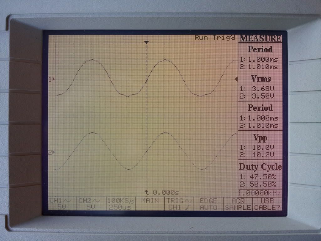
When you scope the SLTPI side you discover that clipping on one peak occurs when drive voltage is 30v pk to pk. As the bias voltage is -15v there is no surprise there. But sadly the moment the sign wave begins to flatten we only have 0.55 Watts RMS power output into 8 ohms.
The other channel starts this behaviour at 57.6v Peak to peak, which means that the CF driver can handle driving the grid as much as 13v positive. But the other arrangement cannot drive any positive grid at all.
This explains for one the constanty rising distortion with power output measured above. From as low as 1/2 a watt I am driving this output stage into A2. This is a testimony to the 6em7 CF as an A2 driver.
So we have that old chestnutt that the sound and the measurements don't coroberate.
I am now listening deliberately at an uncomfortably loud level and the sound is better than when both channels were on CF.
So the situation is that connecting up as SLTPI sounds great but for this output stage is no appropriate.
The CF driver makes this output stage viable, but doesn't sound great at low level (my listening level seems to be half a watt RMS). The SLTP sounds great at 1/2 a watt.
So it seems I haven't yet found out how to use the 1619's. I shouldn't have to drive them in A2 to get power. Time is limited but I shall have to bias them away from A2 and see what power output can be achieved before clipping.
It may be of interest that before positive peak flattening the interstage transformer SW looks considerably better on the SLTPI than it does on the CF connection, considerably.
So the square wave trace and the listening impression I can tell you it is a good way to employ the transformer prior to grid current.
Prior to clipping it pretty well sounds like an SE amp.
Where to go from here? PRobably try a more powerful output valve which I have curves for so I can set it square in the middle of A1 for reasonable power output..
I don't know why I never figured this out before.
Because of the split load transformer phase inverter connection on the right channel, I connected up the scope. What a wally I should have left well alone.
the very sad news is that the output stage to achieve any power at all is running in Class A2.
When you scope the SLTPI side you discover that clipping on one peak occurs when drive voltage is 30v pk to pk. As the bias voltage is -15v there is no surprise there. But sadly the moment the sign wave begins to flatten we only have 0.55 Watts RMS power output into 8 ohms.
The other channel starts this behaviour at 57.6v Peak to peak, which means that the CF driver can handle driving the grid as much as 13v positive. But the other arrangement cannot drive any positive grid at all.
This explains for one the constanty rising distortion with power output measured above. From as low as 1/2 a watt I am driving this output stage into A2. This is a testimony to the 6em7 CF as an A2 driver.
So we have that old chestnutt that the sound and the measurements don't coroberate.
I am now listening deliberately at an uncomfortably loud level and the sound is better than when both channels were on CF.
So the situation is that connecting up as SLTPI sounds great but for this output stage is no appropriate.
The CF driver makes this output stage viable, but doesn't sound great at low level (my listening level seems to be half a watt RMS). The SLTP sounds great at 1/2 a watt.
So it seems I haven't yet found out how to use the 1619's. I shouldn't have to drive them in A2 to get power. Time is limited but I shall have to bias them away from A2 and see what power output can be achieved before clipping.
It may be of interest that before positive peak flattening the interstage transformer SW looks considerably better on the SLTPI than it does on the CF connection, considerably.
So the square wave trace and the listening impression I can tell you it is a good way to employ the transformer prior to grid current.
Prior to clipping it pretty well sounds like an SE amp.
Where to go from here? PRobably try a more powerful output valve which I have curves for so I can set it square in the middle of A1 for reasonable power output..
"Two things are infinite, the universe and human stupidity, and I am not yet completely sure about the universe." – Albert Einstein
-
Paul Barker
- Social Sevices have been notified
- Posts: 8992
- Joined: Mon May 21, 2007 9:42 pm
#132
Having read reports of 4p1l push pull at 8W less than 1% distortion, I am currently thinking bring in the 4p1l project early. Reduce the B+ change the valve bases, adjust the filament supply.
Onwards and upwards.
Onwards and upwards.
"Two things are infinite, the universe and human stupidity, and I am not yet completely sure about the universe." – Albert Einstein
-
Cressy Snr
- Amstrad Tower of Power
- Posts: 10582
- Joined: Wed May 30, 2007 12:25 am
- Location: South Yorks.
#133
Might be the best thing to do Paul, shouldn't take that long either.Paul Barker wrote:Having read reports of 4p1l push pull at 8W less than 1% distortion, I am currently thinking bring in the 4p1l project early. Reduce the B+ change the valve bases, adjust the filament supply.
Onwards and upwards.
Going from AC/P1 to KT120 only took me 3 hours.
With your breadboard, it should take less.
Sgt. Baker started talkin’ with a Bullhorn in his hand.
-
Paul Barker
- Social Sevices have been notified
- Posts: 8992
- Joined: Mon May 21, 2007 9:42 pm
#134
Decided to persevere with the 1619's.
So I adjusted the bias of the output stage to produce most power output before visible clipping. That was arrived at with a bias of -24v Anode voltage of 312v. Static no signal current 54 mA.
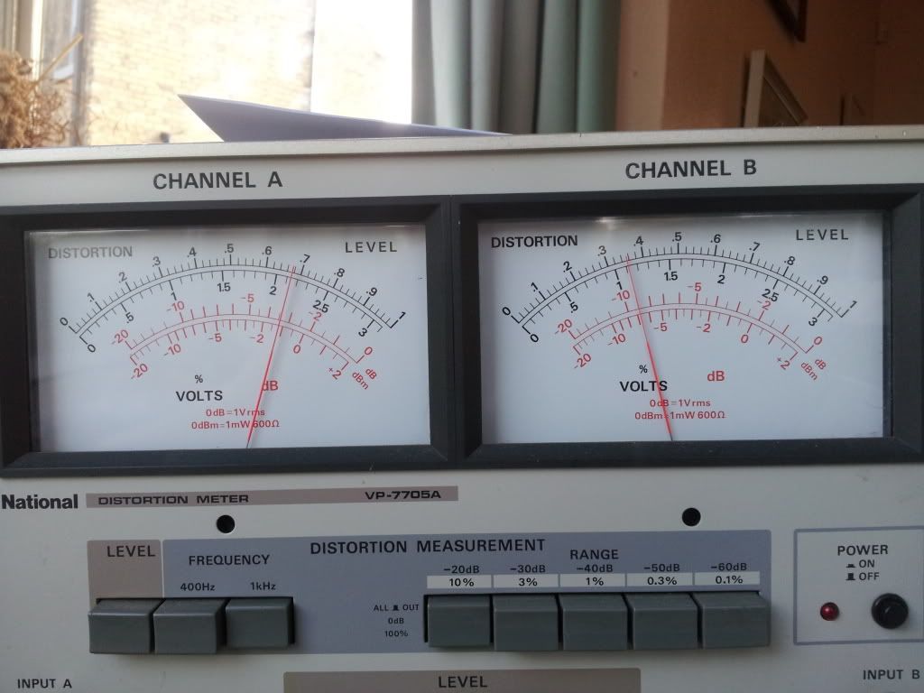
At this operating point power output is 2 watts RMS Distortion 5.5% into 8k Peak to Peak load.
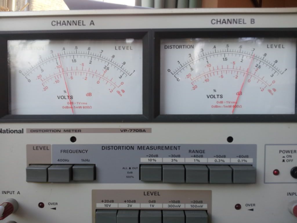
At the same operating point the CF side is very unhappy. 10% distortion.
To double check I switched channels of the distortion analyser it is definately a huge difference. Go figure?
On the chart the vertical axis is both distortion as a % and power as a Watt.
Ignore the numbers on the horizontal axis the spreadsheet made those up.
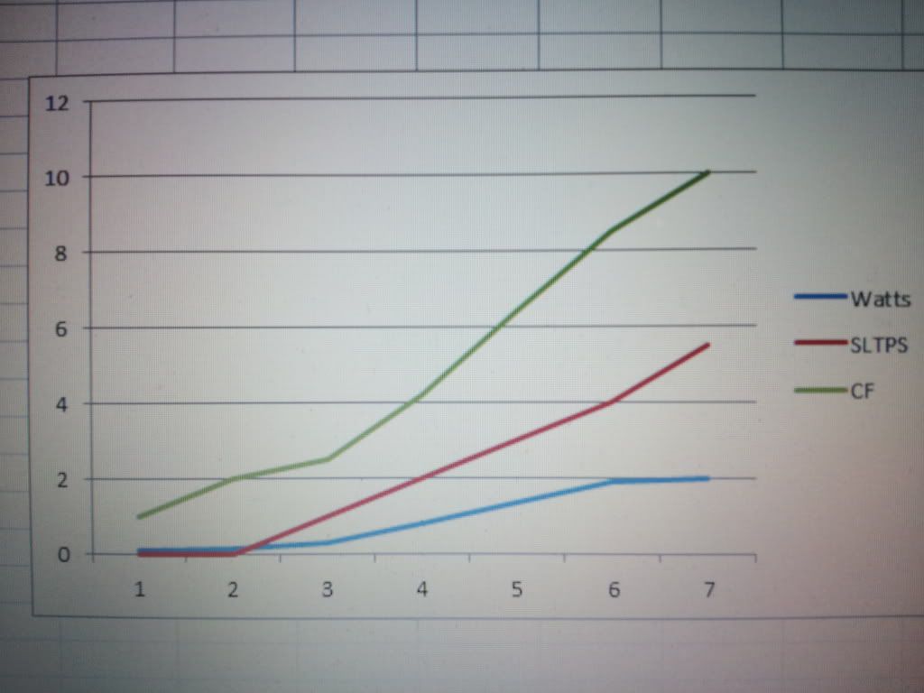
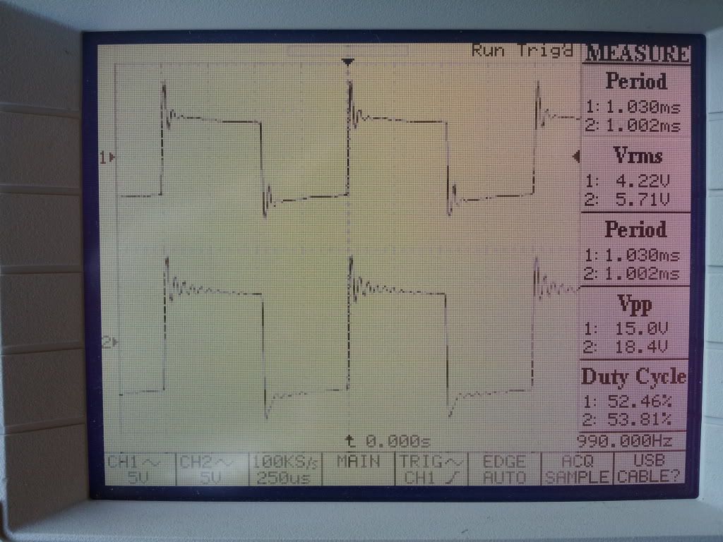
Bottom trace is the SLTPS Top trace the CF On the SW apart from the obvious ringing the Cf version indicates not enough bass, the SLTPS indicates good HF and LF performance except it rings. At the moment I am not well placed to find resistors which mitigate the ringing as all the resistors are at the lockup. The badly distorted top trace may look nice as it is rounded but this is the distortion. It appears to be made of THD there is no evidence of a dominant 2nd or a dominant 3rd. It is an even spread of distortion. After the two watts the SLTPS flattens at the bottom half wave which demonstrates going across into grid current which it is incapable of driving.
2 Watts might seem to be a very disapointing result, but compare that with the fact my 0.7 watt amp is all I need at home, it is a step up.
Clearly the 1619 on 1.6v filament voltage is a very low power triode except when driving it into grid current which it is very happy with anbd produces good results. I ended up down this road because of the decision to try the transformer differently.
To keep to this form of transformer useage I would need to decide on a different valve. These OPT's are 8k so that limits the choices. If I had sufficient PX25's those would go in right away. This very night.
45's are a possibility, but they are at the lockup. (Not at the bottom of the garden; 5 miles away). The beauty of the 45's is they would take this filament supply, but I would need to drop B+ a tad.
801a would be great to try but present filament supply is useless for them.
So I adjusted the bias of the output stage to produce most power output before visible clipping. That was arrived at with a bias of -24v Anode voltage of 312v. Static no signal current 54 mA.
At this operating point power output is 2 watts RMS Distortion 5.5% into 8k Peak to Peak load.
At the same operating point the CF side is very unhappy. 10% distortion.
To double check I switched channels of the distortion analyser it is definately a huge difference. Go figure?
On the chart the vertical axis is both distortion as a % and power as a Watt.
Ignore the numbers on the horizontal axis the spreadsheet made those up.
Bottom trace is the SLTPS Top trace the CF On the SW apart from the obvious ringing the Cf version indicates not enough bass, the SLTPS indicates good HF and LF performance except it rings. At the moment I am not well placed to find resistors which mitigate the ringing as all the resistors are at the lockup. The badly distorted top trace may look nice as it is rounded but this is the distortion. It appears to be made of THD there is no evidence of a dominant 2nd or a dominant 3rd. It is an even spread of distortion. After the two watts the SLTPS flattens at the bottom half wave which demonstrates going across into grid current which it is incapable of driving.
2 Watts might seem to be a very disapointing result, but compare that with the fact my 0.7 watt amp is all I need at home, it is a step up.
Clearly the 1619 on 1.6v filament voltage is a very low power triode except when driving it into grid current which it is very happy with anbd produces good results. I ended up down this road because of the decision to try the transformer differently.
To keep to this form of transformer useage I would need to decide on a different valve. These OPT's are 8k so that limits the choices. If I had sufficient PX25's those would go in right away. This very night.
45's are a possibility, but they are at the lockup. (Not at the bottom of the garden; 5 miles away). The beauty of the 45's is they would take this filament supply, but I would need to drop B+ a tad.
801a would be great to try but present filament supply is useless for them.
Last edited by Paul Barker on Wed Jun 05, 2013 9:53 pm, edited 1 time in total.
"Two things are infinite, the universe and human stupidity, and I am not yet completely sure about the universe." – Albert Einstein
-
Paul Barker
- Social Sevices have been notified
- Posts: 8992
- Joined: Mon May 21, 2007 9:42 pm
#135
Tonight I substituted the 1619 with the 45 on the better channel. This demonstrated that the 1619 is a reasonable substitute triode connected. But it has more gain. The 45 is 3% distorted straight away, and at 5% distortion produces 2.75 watts. After that it goes ragged rapidly.
I am sat here asking myself why am I not just building an se amp with the 2a3 for this power?
The biggest issue seems to be the 8k transformers, 4 or 5k would have suited more valve chocies, 8k is not optimal load for the 45. It would be nice for the 801a but I couldn't then use this same filament supply. I suppose it has to be done another night.
"Two things are infinite, the universe and human stupidity, and I am not yet completely sure about the universe." – Albert Einstein