It is about time I built a push pull amplifier

What people are working on at the moment
Post Reply
User avatar
Paul Barker
Social Sevices have been notified
Posts: 8997
Joined: Mon May 21, 2007 9:42 pm

#1 It is about time I built a push pull amplifier

Post by Paul Barker »

Some recent budget purchases have conspired together to change my direction, so the it's about time I built something more and a watt thread isn't relevant for this new design but remains unfinished because a more powerful Se amp remains on the table.

It is a budget project, not a best amp anyone could ever make. No disrespect to anyone but both sets of transformers were obtained cheaply and I am sure will make a good sounding project, which yes surely would be improved with more expensive iron.

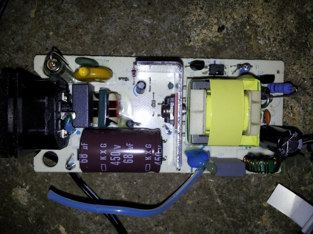
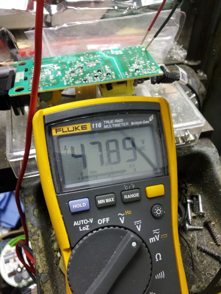
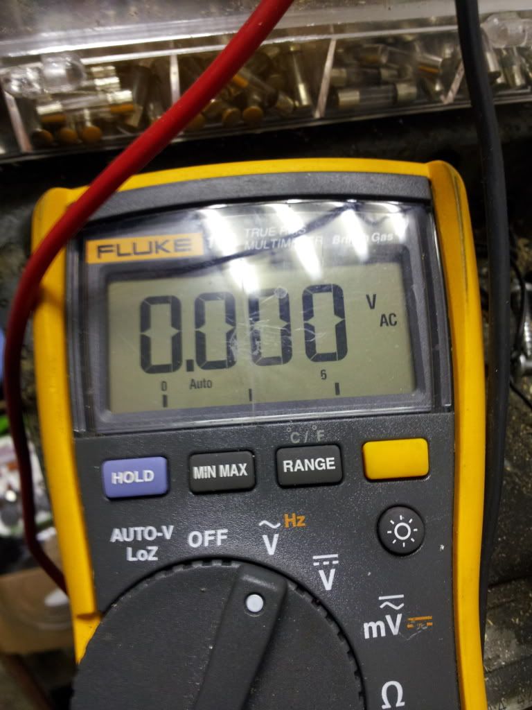
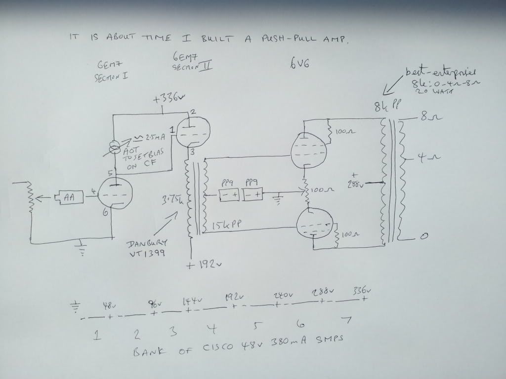
So as a digression into push pull. I thought if I hold on to my loved 6em7 I can direct couple the VA to the driver using the classic methods. The Cisco power supply discovered link at bottom of page, allowing us to pick off voltages wherever we wish.

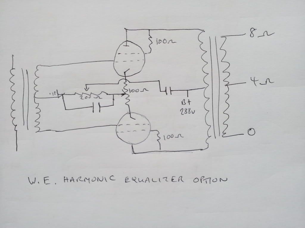
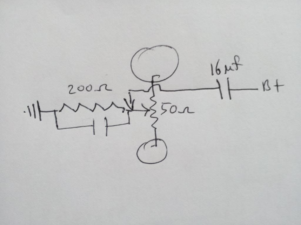
I would have liked to have incorporated WE harmonisation but am unfamiliar with it. I realise it was used by WE at the interstage and at the output stage transformers, but a scan of their circuits has left me somewhat awestruck at the apparent complexity. further reading on the matter implies it requires careful adjustment and at any given signal level it will give a different result. I imagine some form of adjustment plus connection to Andrews distortion analyser would produce fruit. But rather than just plump for it in an amateur way I shall await suggestions from the experienced in these matters.

It has occured to me through the process that a pentode VA would be beneficial in this case, such as that I used in the 6v6 guitar amp project. But the ease of using a single octal plug in the 6em7 for both sections prior to the interstage satisifes my need for simplicity and speed.

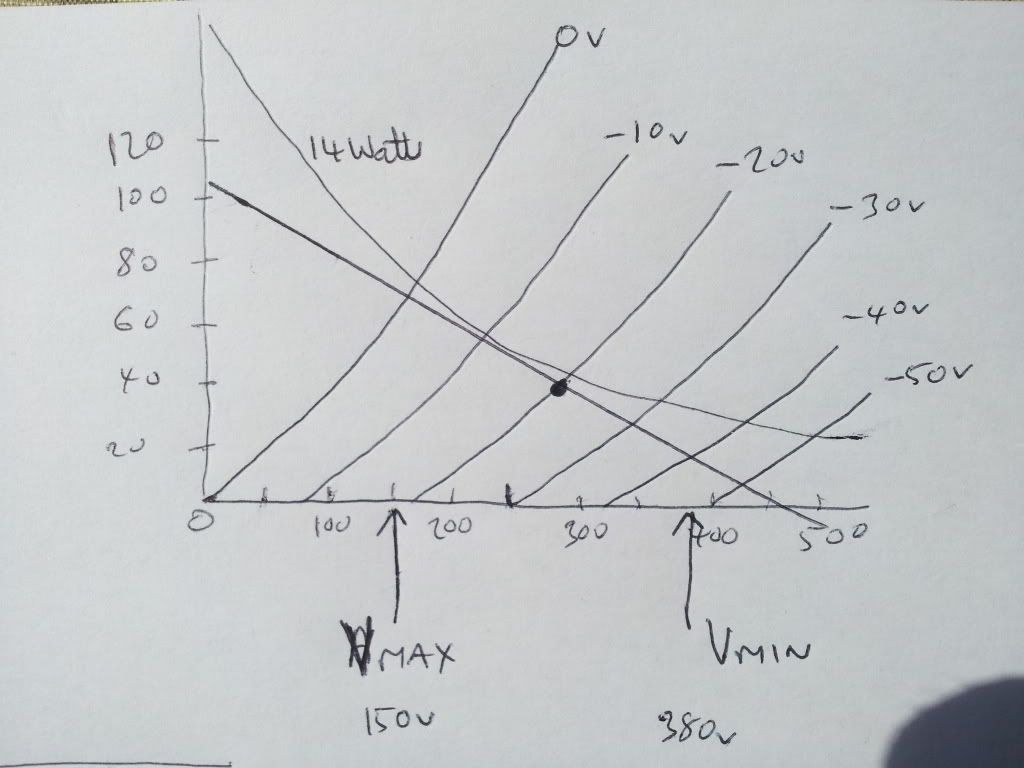
the output stage has adjustment on the cathode for current balancing. You could add a small fixed resistor to each leg for measurement. I would be content to use the opt primary (having first established dc resistance of each leg to calculate current). The majority of the bias is fixed for the simple reason that I don't mind allowing the output stage to slip over into AB2 marginally at peaks, though it is primarily biased for maximum power in A1. So in short it is an A1 design which will clip gracefully like does an SET.

Image

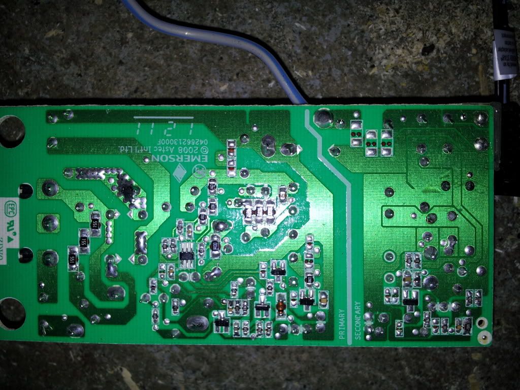
Cisco power first seen here.
"Two things are infinite, the universe and human stupidity, and I am not yet completely sure about the universe." – Albert Einstein
User avatar
Paul Barker
Social Sevices have been notified
Posts: 8997
Joined: Mon May 21, 2007 9:42 pm

#2

Post by Paul Barker »

On a rough calculation the anode to anode voltage goes from 150v to 380v the load is 8k so power in class A1 is (230 X 230)/8,000 = 6.6 watts. This may sound optimistic, but it's there in the calc. When you look at the curves you can see that if the driver swing exceeds class A the valve can survive a further 10v positive and 10v negative to remain in class A, all be it A2. At this there would be about 12mA of grid current which would alter the bias by 6v across the 400 DCohm IT secondary so we are going to see distortion on the positive half. But we do have headroom and can tolerate a little overdrive compared to the normally sudden clipping in class A push pull. Had I intersepted the interstage with a pair of CF's we could achieve decent power in Class A2 push pull. theoretically if we can push the grid to +20v we would see perhaps 60v to 500v anode to anode, so 24 watts in A2 push pull, without crossing into switch off on either triode (AB2). Maximum grid current would then become nearly 20mA. Probably worth trying.
Image
Last edited by Paul Barker on Sat Apr 13, 2013 12:01 pm, edited 1 time in total.
"Two things are infinite, the universe and human stupidity, and I am not yet completely sure about the universe." – Albert Einstein
User avatar
Nick
Site Admin
Posts: 15759
Joined: Sun May 06, 2007 10:20 am
Location: West Yorkshire

#3

Post by Nick »

Paul Barker wrote:On a rough calculation the anode to anode voltage goes from 150v to 380v the load is 8k so power in class A1 is (230 X 230)/8,000 = 6.6 watts.
Image
You would be better to draw some push pull curves.
Whenever an honest man discovers that he's mistaken, he will either cease to be mistaken or he will cease to be honest.
User avatar
Paul Barker
Social Sevices have been notified
Posts: 8997
Joined: Mon May 21, 2007 9:42 pm

#4

Post by Paul Barker »

Nick wrote:
You would be better to draw some push pull curves.
If you stay in Class A there is no benefit.
"Two things are infinite, the universe and human stupidity, and I am not yet completely sure about the universe." – Albert Einstein
User avatar
Paul Barker
Social Sevices have been notified
Posts: 8997
Joined: Mon May 21, 2007 9:42 pm

#5

Post by Paul Barker »

The battery bias of the output stage could hit problems if transients drive grid current. Not sure an alkaline pp9 can tolerate any charge current. If I used rechargeables, the bias would be different but this could be fixed by adapting the cathode balance pot.

The action of grid current would then be interesting.

Maximum grid current for 24 watts power out would be 20mA so the rechargeables would need to tolerate 20mA of pulsed charge. How quickly they respond in voltage to the sudden charge current is an issue, if they lag in response distortion increases. If they raise voltage due to charge current in real time they would ever so slightly mitigate the distortion created on positive peaks by the bias voltage lost across the IT secondary.

I think we are talking loads of positive peak distortion at any rate. But at some point between 6.6 watts and 24 watts the sound would be more suited to a guitar amp than an audio amp.
"Two things are infinite, the universe and human stupidity, and I am not yet completely sure about the universe." – Albert Einstein
User avatar
Cressy Snr
Amstrad Tower of Power
Posts: 10582
Joined: Wed May 30, 2007 12:25 am
Location: South Yorks.

#6

Post by Cressy Snr »

Sounds like a plan Paul, providing you don't talk yourself out of it like I usually do :lol: :lol:

6W is about what the EL84 is delivering at the moment with a following wind.
Hope you can get it to Owston.
Sgt. Baker started talkin’ with a Bullhorn in his hand.
User avatar
Paul Barker
Social Sevices have been notified
Posts: 8997
Joined: Mon May 21, 2007 9:42 pm

#7

Post by Paul Barker »

Harmonic Equaliser option.

Question is the voltage devision of 200 ohm and 50 ohm sufficiently suitable anyway for harmonic equaliser? Or should the B+ cap intercept the 200 ohm leg.

If so does the cathode bypass cap need to join at the wiper or can it remain as I have drawn it?

Harmonic equaliser cap value? 8? 16? proportion of cathode bypass?

Image
"Two things are infinite, the universe and human stupidity, and I am not yet completely sure about the universe." – Albert Einstein
User avatar
Nick
Site Admin
Posts: 15759
Joined: Sun May 06, 2007 10:20 am
Location: West Yorkshire

#8

Post by Nick »

I think you want the lower cap to be to the wiper. There will be no signal across the pot the way you have drawn it because the cap will bipass it.
Whenever an honest man discovers that he's mistaken, he will either cease to be mistaken or he will cease to be honest.
User avatar
Paul Barker
Social Sevices have been notified
Posts: 8997
Joined: Mon May 21, 2007 9:42 pm

#9

Post by Paul Barker »

Actually looking at the WE92 circuit the voltage devision is 85 ohm against 695 ohm the cap value is 16uF.

So a division of 50 ohm against 200 ohm isn't going to cut the mustard (assuming similar potential divide would be about right for any amp.

So:-
Image

Regarding the use of a cathode bypass capacitor the following paper gives a thorough evaluation, which appears to conclude that on the whole the capacitor reduces IM distortion in Class A. Robert M. Mitchel.
"Two things are infinite, the universe and human stupidity, and I am not yet completely sure about the universe." – Albert Einstein
User avatar
Paul Barker
Social Sevices have been notified
Posts: 8997
Joined: Mon May 21, 2007 9:42 pm

#10

Post by Paul Barker »

Nick wrote:I think you want the lower cap to be to the wiper. There will be no signal across the pot the way you have drawn it because the cap will bipass it.
Good point.
"Two things are infinite, the universe and human stupidity, and I am not yet completely sure about the universe." – Albert Einstein
User avatar
slowmotion
Old Hand
Posts: 282
Joined: Fri Aug 21, 2009 4:07 pm
Location: Norway

#11

Post by slowmotion »

Thanks for the Robert M. Mitchel link,
I will read that tomorrow.

There are also some Bell Labs patents re the Harmonic Equalizer,
I'll see if I can dig them up.
I know they are around here - somewhere - .
- Jan -
User avatar
Paul Barker
Social Sevices have been notified
Posts: 8997
Joined: Mon May 21, 2007 9:42 pm

#12

Post by Paul Barker »

I had to use a Dremel to cut open the Cisco power supplies.

On inspection there is no adjuster to alter the voltage, so I'll go with what is provided.

There is a small X type cap on the secondary side of it which is grounded. So I lifted it. I can't tell you what a couple of other things are which are also on the same potential. It may be that to connect all these to minus out would do no harm. But as the man who discovered these left it disconnected, we know that works. So I cut mine too since all this surface mount solid state stuff is not my arena.

The output is void of AC down to 0.000 volts. I haven't scoped it. But my meter (oh all right then, British Gas's meter) is acurate.

Image
Image
Image
Image
"Two things are infinite, the universe and human stupidity, and I am not yet completely sure about the universe." – Albert Einstein
User avatar
Paul Barker
Social Sevices have been notified
Posts: 8997
Joined: Mon May 21, 2007 9:42 pm

#13

Post by Paul Barker »

I have slight butterflies about two issues both to do with voltage tensions:-

1/ The interstage primary stands at +192v DC the secondary stands at zero volts. I could lift the whole of the section between interstage and output transformers to +48v (i.e. where you see ground in this part of the schematic would be changed to +48v, and shift the B+ take off up to 336v. So reduce the tension to 144v. Unknown is the effect on earth noise by such radical action. Remember in the power supply there is a 4k resistor across each 48v supply, so nothing is floating about in space. It will remain to be discovered just what sounds best; 0v reference at all ground points or +48v between these transformers. It remains to be discovered whether the Danbury interstages will tolerate the 200v tension.

2/ There has to be a limit of voltage tension which the elements within the 48v modules can themselves tolerate. On the surface, the primary side has no actual ground reference, the only ground reference is via the X type cap on the secondary which is lifted by us. However in the UK neutral is referenced to ground (assuming we aren't using Ali's isolation transformer with this power supply). Now it depends on your household earthing system how well referenced to ground this is, worst case scenario with a TT earth it can be separated a few hundred ohms from the sub station ground, but the "best" pme earthing system has neutral held at substation ground and hosuehold earth held at that same neutral potential, and the neutral also grounded at multiple points along the way, so <1 ohm difference. At any rate, some parts of the primary of this supply is referenced to ground be that via <1 ohm or a couple of hundred ohms (assuming no earth fault <if you have a TT earth go outside and pee on your earth spike now and again>).

So we have a primary and a secondary to this smps. On underside of the board anotated by a line,

Image

Look on the flip side

Image

and see a couple of items bridging this potential difference. there will be a limitation to the voltage tension these components can tolerate.

Now I am only stacking 7 of these critters. Erick Bates has stacked 18.

But we know that at some point the tolerance of these modules shall be discovered. Just in case anyone was thinking there is no limit.
"Two things are infinite, the universe and human stupidity, and I am not yet completely sure about the universe." – Albert Einstein
User avatar
Paul Barker
Social Sevices have been notified
Posts: 8997
Joined: Mon May 21, 2007 9:42 pm

#14

Post by Paul Barker »

I haven't finished exploring Erick Bates' fresh ideas, and decided to build the Optocoupler at last. I previously bought discreat components to make my own LED volume pot, but things have taken me too many years and now components such as these linked have come within the radar of the audio community. though I recall optocouplers being used long time by the radio hams to connect their transmitters to the computer for RTTY. I never explored them for audio. Anyway, have fallen in line now.

My total order from farnel for the selected optocouplers linked, a 6v transformer for all the valves AC heating, the resistors and pots required, the RCA sockets and speaker connectors, came to £96. Ouch! The 7 smps's previously cost £35.

For the time being instead of CCS load on the VA I have ordered a pair of linear 100k pots which should give sufficient adjustment to set bias on the CF and provide sufficient load for adequate voltage amplification. The output stage only requires 20v peak for class A1. There is 1:1 voltage transfer across the interstage.

The interstage may benefit from load resistors on the secondary. these have been left out for the moment as it would require AOT on site of SW and listener approval...Moi! Often this listener prefers the sound of a ringing transformer to a resistorised transformer, but I remain amenable to testing.
Last edited by Paul Barker on Sun Apr 14, 2013 10:22 am, edited 1 time in total.
"Two things are infinite, the universe and human stupidity, and I am not yet completely sure about the universe." – Albert Einstein
User avatar
Nick
Site Admin
Posts: 15759
Joined: Sun May 06, 2007 10:20 am
Location: West Yorkshire

#15

Post by Nick »

Most of these sorts of supplies are designed to withstand 4kv between input and output. Now that is only a short term test (as you know), but I would have thought 400v would be no problem to them for ICAS.
Whenever an honest man discovers that he's mistaken, he will either cease to be mistaken or he will cease to be honest.
Post Reply