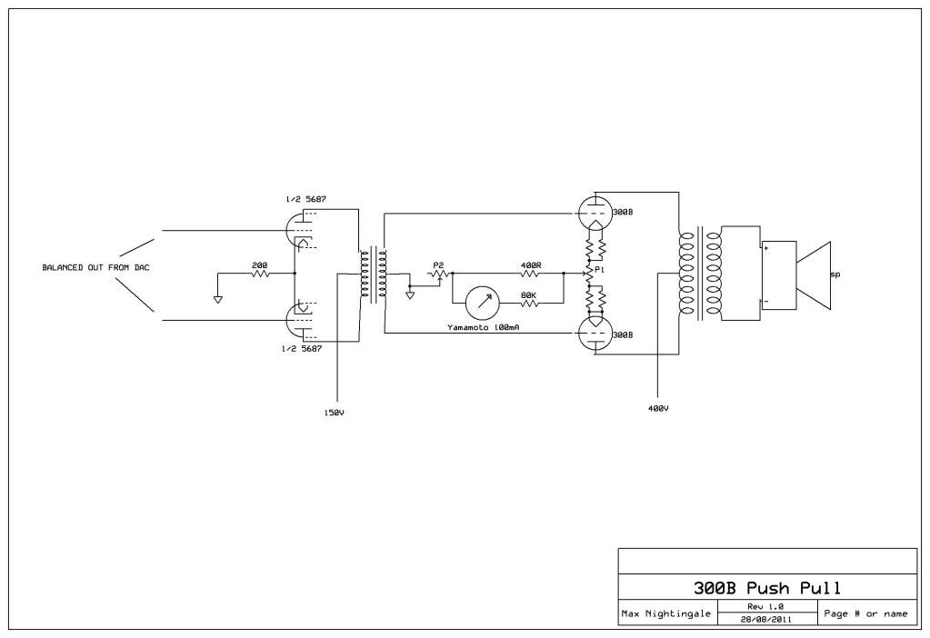
Why don't you monitor each cathode of the 300b's and either use two current sinks one per valve or one current sink where they meet and an adjustable resistor on each branch from the 300b's.
Also ditto Nick on the DAC output but I expect you are onto that.
Yesterday afternoon I read John attwood's very long Triode Mafia thread about small transformers which he tested as DAC outputs. Though in those days theye weren't using the AK4393/6 so the needs were different. Alan Wright was telling them all how important it was to buy reclocking kits from him, and Lynn Ollsen was telling them all how he invented the idea of transformer coupling in 1997 (non of the rest of us apparently ever thought of it) and it was the only way anyone with any sense should now go.
Quite a hillarious thread if you are an observer of human behaviour and you were actually a partaker throughout the period when you can look back and see the blatant chest puffing.
But, one of the things I did glean from the thread was that a few significant people, well Alan Wright anyway did think the low pass filter was necessary. But he conceded that John Attwood maybe got away without needing it because his transformers naturally filterd the 50khz (or whatever frequency it is at) grunge. And that was his excuse for why John didn't like the capacitor coupling.
IF the above is true, perhaps you should in any case consider coupling to the grids of the 5687 through a balanced transformer. OR reinstate the 50khz (or whatever frequency it needs to be) low pass filter.
But no doubt Clive has more wisdom to throw on your plan.
The rest of the topology? Cock on!
The beauty of the plan is that you could convert it to the Steve Bench Single ended style of going balanced right up to the output stage