Schottky bridge problem

We all start somewhere
simon
Thermionic Monk Status
Posts: 5643
Joined: Thu May 24, 2007 11:22 am
Location: People's Republic of South Yorkshire

#1 Schottky bridge problem

Post by simon »

This seems the most appropriate place to post this, so here goes.

I'm playing around with a 7.5V tx with the aim of DC heating the phono I've been working on. (The mains tx has a 6.3V winding which I have been using but I want to use this for the series reg valves for the HT). I thought I'd get the DC heaters up and running with a simple CRC first, then at a later date use a 9V tx and a LM338 or some such.

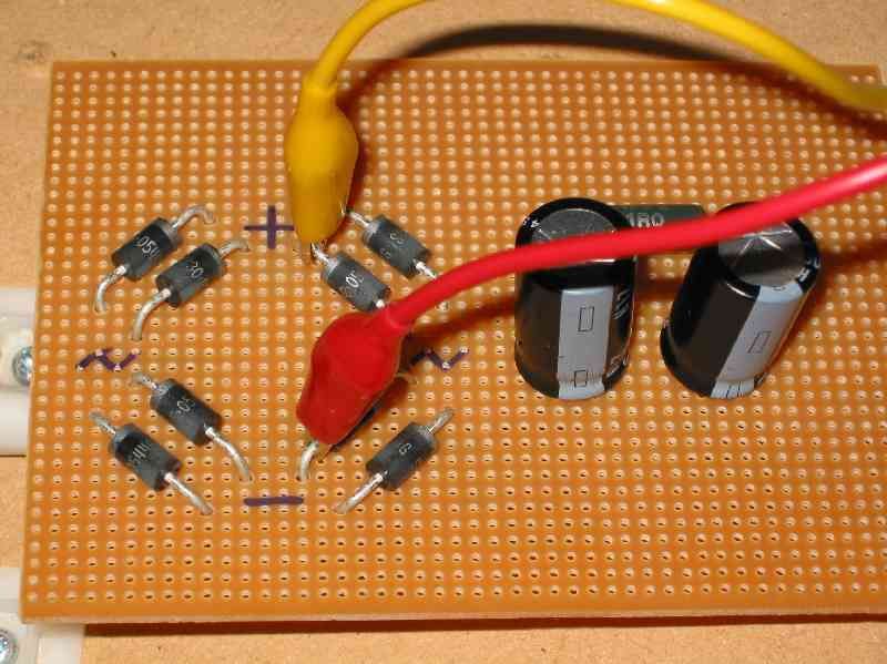
So I've got a bridge made of Schottkys shown here:
Image
Ignore the caps and resistor as I've disconnected them. With a load clipleaded to the + and - of the bridge on the top of the matrix board I get 7.5VDC and 0VAC. Fine.

But when I cliplead to the same + and - on the underside of the matrix board like this: Image
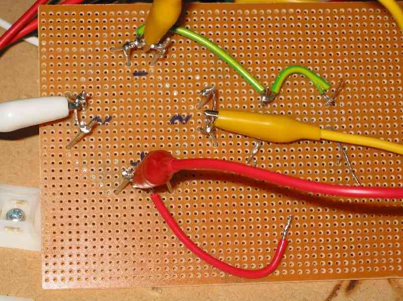
I get 11.5VDC and 24.5VDC. Nothing else has changed, only where I've attached the cliplead to. Clipleading from the top to the cap on the underside also gives me AC. I'm stumped, I can't see what I've done wrong.

Any suggestions?

Cheers,
Simon.
User avatar
Nick
Site Admin
Posts: 15746
Joined: Sun May 06, 2007 10:20 am
Location: West Yorkshire

#2

Post by Nick »

The yellow and red leads are swapped, is it something going on with your meter? What happens if you swap the leads on the top?
Whenever an honest man discovers that he's mistaken, he will either cease to be mistaken or he will cease to be honest.
simon
Thermionic Monk Status
Posts: 5643
Joined: Thu May 24, 2007 11:22 am
Location: People's Republic of South Yorkshire

#3

Post by simon »

Spot on Nick. Changing the leads around on top gives me 15.5VAC and 11.4VDC. Switching the leads round on the underside has a similar result - no AC. Why should changing the way the probes are connected have an effect? Is the meter dodgy?
Clive
Old Hand
Posts: 374
Joined: Tue May 22, 2007 9:17 am
Location: Cheshire, England

#4

Post by Clive »

I expect it's something to do with the way the meter works but also don't forget that what you're calling DC isn't anywhere near properly smoothed, in fact it's not smoothed at all.
Andrew
Eternally single
Posts: 4206
Joined: Thu May 24, 2007 2:18 pm

#5

Post by Andrew »

Yes, its going to have a DC component and an AC component but the AC will be at 100Hz-ish now and won't be anywhere near a sine wave, which means, depending upon your meter and how sophisticated it is, TRUE RMS etc, you'll not be reading what's really there.

cheers,

-- Andrew
simon
Thermionic Monk Status
Posts: 5643
Joined: Thu May 24, 2007 11:22 am
Location: People's Republic of South Yorkshire

#6

Post by simon »

Thanks chaps. I figured that I may get some "AC" reading because of lack of smoothing, but figured this would be half of the DC voltage, say 6ish VAC. How it's 15.5V I don't really understand though. Neither do I understand why changing the probes round should make a difference - surely it should just give me a positive or a negative DC reading?

Geez, I'm confused easily enough as it is without meters doing things I don't expect :lol:. Perhaps it's time to get a new meter.
simon
Thermionic Monk Status
Posts: 5643
Joined: Thu May 24, 2007 11:22 am
Location: People's Republic of South Yorkshire

#7

Post by simon »

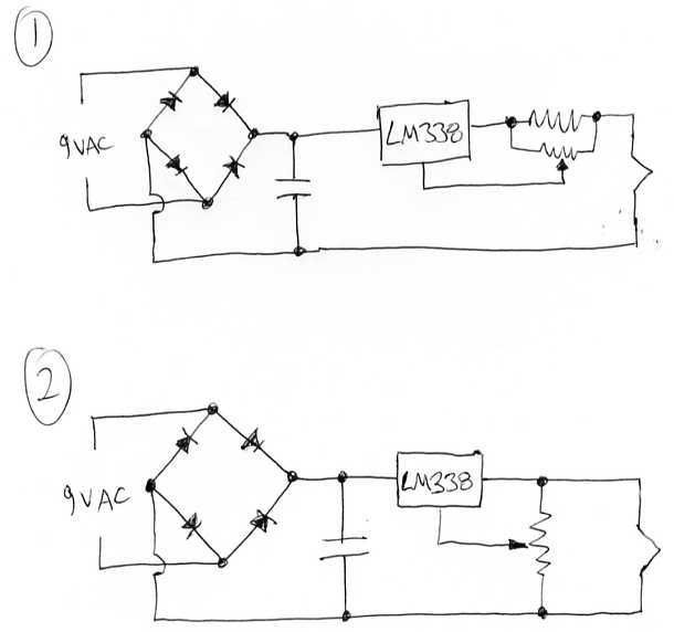
I've spent a bit of a fruitless evening playing with an LM338 trying to regulate the heaters on the phono. I've done the maths and then built schem 1 below.
Image
It wouldn't work so I played with the numbers again, and played with the circuit, but it just wouldn't work properly.

Scratching my head and running out of ideas, I tried MJ's method of using a 150R and 600R divider across the filament with ADJ to the middle and it was nearly right. So I put the 20k pot in in its place as in schem 2 and the voltage dropped out dead easy.

But I figured, if this method is so easy why doesn't everybody do it like this? Presumably there's a down side; what does the panel reckon? :?
User avatar
pre65
Amstrad Tower of Power
Posts: 21399
Joined: Wed Aug 22, 2007 11:13 pm
Location: North Essex/Suffolk border.

#8

Post by pre65 »

Hi-method 1 is how i am doing the PT15 filament on my amp.Just rebuilt the circuit with shotkies as per Nicks suggestion,so i hope it will work. :shock:

Will find out soon.
The only thing necessary for the triumph of evil is for good men to do nothing.

Edmund Burke

G-Popz THE easy listening connoisseur. (Philip)
User avatar
Nick
Site Admin
Posts: 15746
Joined: Sun May 06, 2007 10:20 am
Location: West Yorkshire

#9

Post by Nick »

Ahh, ok, on the phono, 2 is better, its working as a voltage regulator, thats what you need for parallel connected heaters,

1, is a current regualtor, good for a single DHT, or if you have valves that all need the same current on their heaters. In which case you connet them in series and run them at a voltage that provides the required current.
Whenever an honest man discovers that he's mistaken, he will either cease to be mistaken or he will cease to be honest.
simon
Thermionic Monk Status
Posts: 5643
Joined: Thu May 24, 2007 11:22 am
Location: People's Republic of South Yorkshire

#10

Post by simon »

Ah, geddit. Thanks Nick.
simon
Thermionic Monk Status
Posts: 5643
Joined: Thu May 24, 2007 11:22 am
Location: People's Republic of South Yorkshire

#11

Post by simon »

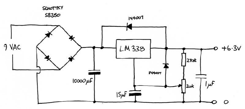
This is the regulated heater supply I ended up building for the phono:

Image

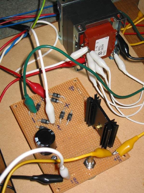
which looks like this:

Image

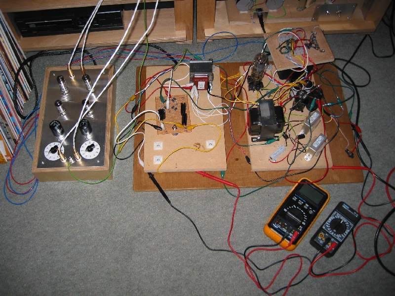
and this:

Image

I should have built it step by step and listened to each bypass cap etc. but I just put them in anyway. Not sure why the 270R resistor on top of the pot, it seemed like a good idea at the time. The 10000uF cap is only rated at 16V as it's all I have - probably should be 25V to be sure.

I've only had chance to listen to one side of a record (and I know the phono takes a few minutes to warm up) but my initial impression is I'm impressed. Although the hum didn't seem that loud before it's now very quiet. There's a little left which I think may be the HT. What struck me first was the deeper and more extended bass (no doubt more obvious because of the particularly bassy start to the record). The lowered noise floor really seems to make a difference in this respect. There's more detail coming through too, stuff I haven't heard before. What surprised me was the extra drive the music had. I can only guess that this is the subtleties of the microdynamics that James always talks of.

Hopefully I'll get a longer listening session tomorrow, and it will still sound as good. Next the HT reg. :D
User avatar
Dave the bass
Amstrad Tower of Power
Posts: 12276
Joined: Tue May 22, 2007 4:36 pm
Location: NW Kent, Darn Sarf innit.

#12

Post by Dave the bass »

I'm gonna organize a whip round at WF and buy you some solder :D It's really good stuff y'know, like electronical glue :wink:

DTB
"The fat bourgeois and his doppelganger"
User avatar
Nick
Site Admin
Posts: 15746
Joined: Sun May 06, 2007 10:20 am
Location: West Yorkshire

#13

Post by Nick »

It's really good stuff y'know, like electronical glue
Ahh, but clipleads are like electronic velcro.
Whenever an honest man discovers that he's mistaken, he will either cease to be mistaken or he will cease to be honest.
simon
Thermionic Monk Status
Posts: 5643
Joined: Thu May 24, 2007 11:22 am
Location: People's Republic of South Yorkshire

#14

Post by simon »

That's really kind of you Dave. But, I'm okay for solder, beer would be good :).
Andrew
Eternally single
Posts: 4206
Joined: Thu May 24, 2007 2:18 pm

#15

Post by Andrew »

Hi Simon,

Good to hear its coming on, I assume you only DC'd the pentodes, or was it the whole shebang?

Have you tried the LED's yet?

cheers,

-- Andrew
Post Reply