I'm playing around with a 7.5V tx with the aim of DC heating the phono I've been working on. (The mains tx has a 6.3V winding which I have been using but I want to use this for the series reg valves for the HT). I thought I'd get the DC heaters up and running with a simple CRC first, then at a later date use a 9V tx and a LM338 or some such.
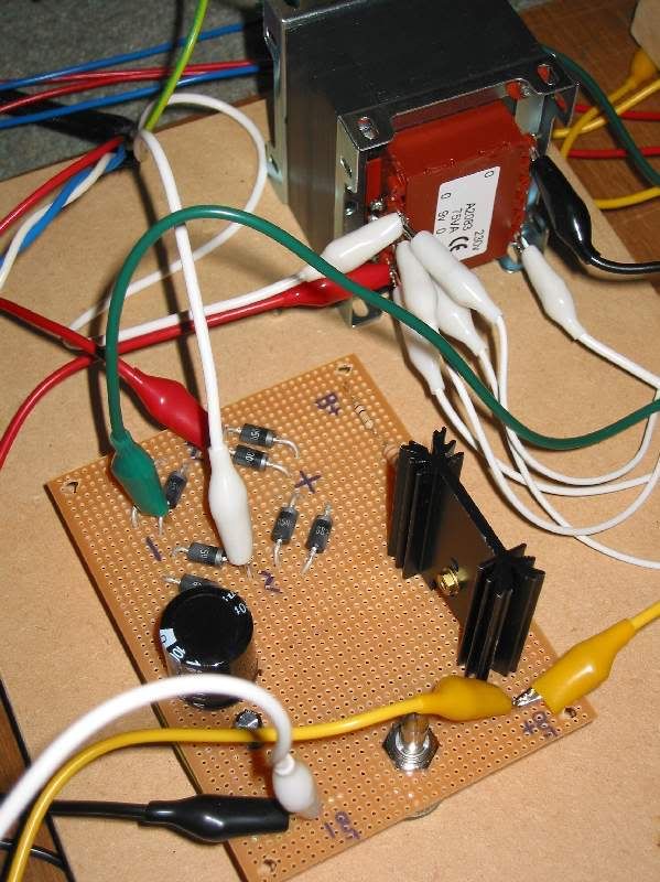
So I've got a bridge made of Schottkys shown here:
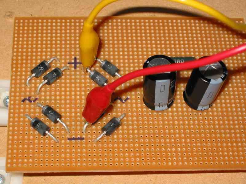
Ignore the caps and resistor as I've disconnected them. With a load clipleaded to the + and - of the bridge on the top of the matrix board I get 7.5VDC and 0VAC. Fine.
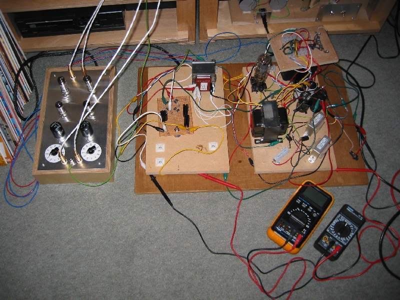
But when I cliplead to the same + and - on the underside of the matrix board like this:
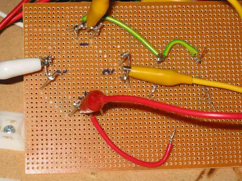
I get 11.5VDC and 24.5VDC. Nothing else has changed, only where I've attached the cliplead to. Clipleading from the top to the cap on the underside also gives me AC. I'm stumped, I can't see what I've done wrong.
Any suggestions?
Cheers,
Simon.