4P1L

If they glow, this is the place to be
User avatar
Paul Barker
Social Sevices have been notified
Posts: 8988
Joined: Mon May 21, 2007 9:42 pm

#1 4P1L

Post by Paul Barker »

Image

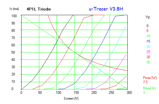
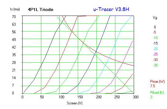
Now this is where it gets really exciting: Let me regraph it for you:

Image
Image
Image


1.7 Watts power out on a 3k load in class A1. A2 curves are available but I can't provide them at the moment. 3K looks alright, I thought a lot of people would have 3k transformers so provided that nugget. I have 4k5 transformers which would be ideal. Looks like 4k5 would give a little more power and less 2nd harmonic.

You should get 2.6 watts in A2.

There is every possibility it may sound like a PX25. Lower on power I grant you, but characteristics virtually identical.
"Two things are infinite, the universe and human stupidity, and I am not yet completely sure about the universe." – Albert Einstein
User avatar
IslandPink
Amstrad Tower of Power
Posts: 10041
Joined: Tue May 29, 2007 7:01 pm
Location: Denbigh, N.Wales

#2

Post by IslandPink »

There's been a lot of excitement about them over on DIY Audio.
One of the advantages is you can use them in filament bias, not many output valves which lend themselves to that .

PSE also makes sense, would work quite nicely with the old WAD 2A3 PSE output transformers.

Ps. Pmax (diss) as triode is 9W by the way .
"Once you find out ... the Circumstances ; then you can go out"
User avatar
Paul Barker
Social Sevices have been notified
Posts: 8988
Joined: Mon May 21, 2007 9:42 pm

#3

Post by Paul Barker »

IslandPink wrote:
Ps. Pmax (diss) as triode is 9W by the way .
OK better still then.
"Two things are infinite, the universe and human stupidity, and I am not yet completely sure about the universe." – Albert Einstein
JamesD
Old Hand
Posts: 997
Joined: Tue Oct 09, 2007 4:26 pm
Location: North Yorkshire

#4

Post by JamesD »

Interesting! Andy Evans has gone all over to the 4P1L and this rather supports him in that!

J
User avatar
Nick
Site Admin
Posts: 15751
Joined: Sun May 06, 2007 10:20 am
Location: West Yorkshire

#5

Post by Nick »

Got the valves Paul if someone can point me towards the traces you want I will get on with it.
Whenever an honest man discovers that he's mistaken, he will either cease to be mistaken or he will cease to be honest.
User avatar
IslandPink
Amstrad Tower of Power
Posts: 10041
Joined: Tue May 29, 2007 7:01 pm
Location: Denbigh, N.Wales

#6

Post by IslandPink »

The concept was here :
http://www.audio-talk.co.uk/phpBB2/view ... &start=195
So we're talking pentode mode ;
I'm looking for about 150V on G2 .
"Once you find out ... the Circumstances ; then you can go out"
User avatar
Nick
Site Admin
Posts: 15751
Joined: Sun May 06, 2007 10:20 am
Location: West Yorkshire

#7

Post by Nick »

Is this what you want?

Image
Whenever an honest man discovers that he's mistaken, he will either cease to be mistaken or he will cease to be honest.
User avatar
IslandPink
Amstrad Tower of Power
Posts: 10041
Joined: Tue May 29, 2007 7:01 pm
Location: Denbigh, N.Wales

#8

Post by IslandPink »

I think so , I haven't yet sat down and looked at the normal curves for g2=150 without this alternative connection. They don't look much different at first sight . Could you do a diagram of exactly what you set up ?

It just occured to me that if this sounds good, then it's the simplest solution to supply of G2 on a pentode when used as the first valve on a phono . We were discussing how a cathode follower from the triode in a triode/pentode combo could be used to decouple G2 - avoiding caps or VR tubes, you remember ? If it works, then this is even simpler , with low noise.
"Once you find out ... the Circumstances ; then you can go out"
User avatar
Paul Barker
Social Sevices have been notified
Posts: 8988
Joined: Mon May 21, 2007 9:42 pm

#9

Post by Paul Barker »

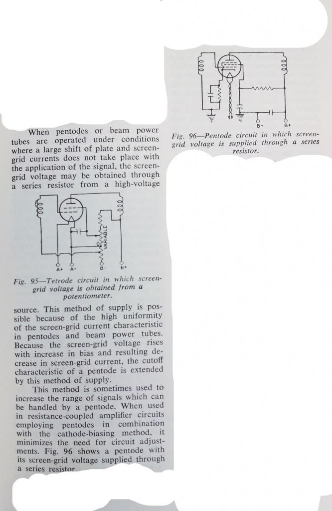
I had a chance to trace the effect of the resistor load on the screen.Fig.96

I am surprised.

Image
Image
Image
Image
Image
Image
"Two things are infinite, the universe and human stupidity, and I am not yet completely sure about the universe." – Albert Einstein
User avatar
Nick
Site Admin
Posts: 15751
Joined: Sun May 06, 2007 10:20 am
Location: West Yorkshire

#10

Post by Nick »

I think so , I haven't yet sat down and looked at the normal curves for g2=150 without this alternative connection. They don't look much different at first sight . Could you do a diagram of exactly what you set up ?
I asked if you wanted anything different, and I thought not, so thats just pentode, g2 150v, g3 to cathode.
Whenever an honest man discovers that he's mistaken, he will either cease to be mistaken or he will cease to be honest.
JamesD
Old Hand
Posts: 997
Joined: Tue Oct 09, 2007 4:26 pm
Location: North Yorkshire

#11

Post by JamesD »

Ohh, those raised suppressor ones are interesting with the single resistor to G2...

Thanks!
User avatar
Paul Barker
Social Sevices have been notified
Posts: 8988
Joined: Mon May 21, 2007 9:42 pm

#12

Post by Paul Barker »

I was shocked at the loss of voltage gain, but interested by the peculiarity that it turns distortion (though low) on it's head.

Here is a possible low distortion operating point for a driver with a voltage gain of 17 and an output amplitude of 170v at a ratio of right side to left side of 1.05 which roughly speaking amounts to 1/2 a percent 2nd.

But the peculiarity is the 2nd distortion is 180 degrees out of phase with triode distortion.

Image

I can't decide if it is a good idea. As it will increase normal triode output stages distortion, whereas triode distortion would decrease it. So what do we do with this? Do we use it to drive a pentode output stage?

I suppose one answer is we use it to drive a CF output stage.

Another answer is the distortion is so low we don't worry about it. Find a triode with such low distortion? OK you got me banged to rights in the EF184. But might this not sound better?

the other consideration is cascade two of these for cancellation and obtain a voltage gain of 289. You benefit from the low miller capacitance as an input stage, huge gain and good drive capability.

Nick sorry I saw your question but soldering iron was smoking away at the time and I was busy all evening in discussions with Ronald step by step to get the uTracer fixed. Then once fixed I could just trace what I had in mind anyway.
"Two things are infinite, the universe and human stupidity, and I am not yet completely sure about the universe." – Albert Einstein
User avatar
Paul Barker
Social Sevices have been notified
Posts: 8988
Joined: Mon May 21, 2007 9:42 pm

#13

Post by Paul Barker »

though anecdotally I can say the 6sj7 tret in this way, which I lifted from an old circuit (from when they had working knowledge of these effects) sounded best with this connection compared to the usual voltage devision. I don't recall however whether I tried the VR tube in that particular amp.

Totally different pentode though. Nice sounding VA pentode (6sj7) I have to say.
"Two things are infinite, the universe and human stupidity, and I am not yet completely sure about the universe." – Albert Einstein
JamesD
Old Hand
Posts: 997
Joined: Tue Oct 09, 2007 4:26 pm
Location: North Yorkshire

#14

Post by JamesD »

Wow! Interesting and, as you say, unusual distortion profile. The cascade idea into a CF ouput is a great idea! That makes driving the output transformer easier too...

This great stuff, Paul, its really enabling us to look at how to use a valve outside of the conventional approaches - Great Stuff!!!
User avatar
IslandPink
Amstrad Tower of Power
Posts: 10041
Joined: Tue May 29, 2007 7:01 pm
Location: Denbigh, N.Wales

#15

Post by IslandPink »

Andy Evans' latest circuit :
http://www.diyaudio.com/forums/tubes-va ... se-63.html
Nice !
[ 4P1L IT-coupled into Parallel 4P1L outputs with filament bias ]
"Once you find out ... the Circumstances ; then you can go out"
Post Reply