Page 6 of 11
#76
Posted: Mon Jul 15, 2013 9:55 pm
by Paul Barker
Thanks Andrew but it isn't up to the shoddy standard. I drilled a hole in the wrong place for a start. I meant to place the green connectors at 20mm intervals and drilled one after 10 mm. Where's Wally?
#77
Posted: Wed Jul 17, 2013 8:47 am
by lens42
Paul Barker wrote:I put the inductor on stilts so I could use thick wire, as to wrap wire around as suggested it has to be very thin to fit through the pcb holes, and is as useful as a chocolate fireguard at dissipating heat. So I stood it off with thick wire across which all the feared heat will dissipate. The first indcutor I did with the wire thin enough to pass through the pcb and it seemed to be a worthless effort.
nickds1 wrote:I read this in the manual but it seems a silly idea to me.
It's not really on legs, it's just elevated by the thickness of the wire. I don't think it's silly to use wire as shown in the instructions. Beside preventing the pads from lifting (maybe not needed if you NEVER drop the box) it also makes the connection under the inductor much easier to see and get a soldering iron on to. I do a lot of surface mount work and find this very clever.
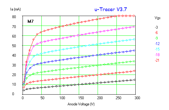
#78 M7 & A2 Curves.
Posted: Wed Jul 17, 2013 7:08 pm
by James
I have tried using the Screen supply to provide positive grid bias to get some A2 curves on an 826. Obviously I could only run one curve at a time, but it appears to work. I think Ronald is looking to incorporate the facility to sweep Va for stepped Vs in the next version of his GUI so will enable a set of curves to be traced in the same way as with negative grid voltages. I have not tried Nick's alternative GUI yet so am not sure if it has this feature?
I didn't save the images but plotting the screen current shows grid current nicely.
Here is the abbreviated series......
#79
Posted: Wed Jul 17, 2013 7:10 pm
by James
Ronald has pointed out that the DAC process is not very accurate at low voltages, so thing are a bit wobbly below about 10v, but it does appear to work.
Here is the 826 in action.
#80
Posted: Wed Jul 17, 2013 10:44 pm
by Paul Barker
Great James.
We are in Warwick tonight or I would be straight down to the man Cave tracing the M7.
#81
Posted: Thu Jul 18, 2013 10:48 pm
by Paul Barker
Excited of Scarborough.
Had a great day watching the love of my life turn from a graduand to a Graduate Master of Careers Information Advice and Guidance in Higher Education with Merit at the University of Warwick.
On return couldn't wait to give Class A2 a try.
The way James did it looked horrible, the curves were saw toothed. I can only assume at each anode voltage step the screen voltage supply hadn't recovered the grid current. Also it gets off to a rocky start as seen on James's curves.
So I decided it could be done on the fly. I hooked up a seperate power supply capable of 30v 2amp.
To get the plot on the GUI I told the uTracer to provide the same volts but make them negative, though I didn't connect to the uTracer grid supply.
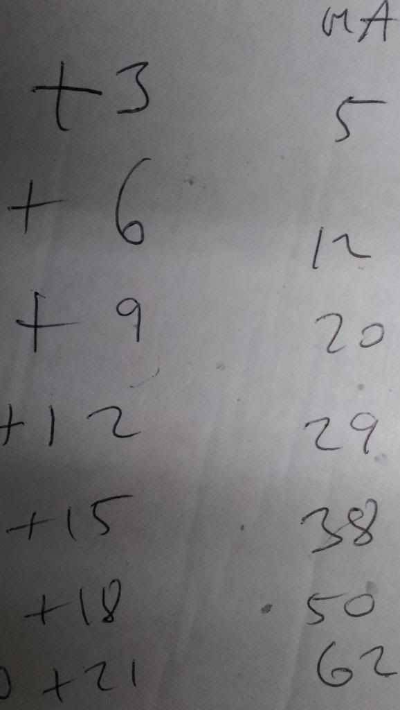
By hand I set the grid volts with my seperate supply. At each step I wrote down the grid current by reading the current display on my supply.
We now have the first available anywhere in the world characteristic curves for the rare DHT made in Copenhagen the M7.

#82
Posted: Thu Jul 18, 2013 10:54 pm
by IslandPink
Nice curves !
#83
Posted: Thu Jul 18, 2013 11:15 pm
by Paul Barker
But not something we can really use in audio.
I can see a 7k loadline biased at +4.5v 175v on the anode for 1 watt in Class A2 with maximum swing up to the +12v grid line and down to zero volts at 300v extension for the 30mA maximum grid current.
You'd get further with another valve but it is often the case such oddball characteristics bring a sweet sound.
So it shall be tried!
#84
Posted: Thu Jul 18, 2013 11:28 pm
by Paul Barker
#85
Posted: Fri Jul 19, 2013 7:43 am
by Paul Barker
WARNING!
Don't try the above.
Ronald has told me my error. I am loading the grid the whole time.
That answers a question which lurked in my mind. Gid current curves would show the very high grid current figures I found when anode voltage is low but much less current when anode voltage is high.
The uTracer only bursts the anode voltage out briefly so all the time I put a positive voltage on the grid it takes all the electrons as if there were no anode voltage.
So
1/ Good news the grid current figures are nothing like reality. I wandered why they were so high relative to anode current. which precipitates the downside:
2/ The grid current I measured represent the permanent use of the grid as an anode.
very quickly burned out grid would ensue.
So where do we go from here?
Stick with Ronald's screen supply. In time he shall adapt the GUI to work this way.
What I called the saw tooth we could live with inititally, but Ronald is also working on that. Though I am sure it is hard to eliminate.
We could easily smooth out the positive grid lines in our thinking.
the fact that the grid current of this valve won't be anything like I measured puts it into contention for more than 1 watt power output.
It is the size of a 2a3 and same filament power. We now know the grid is rugged because I abused it immensely the fact I have a working valve at the end of that is testimony to it's resilience.
Once again probably designed for AB2 operation but we could get somewhere in A2 and it might sound good. Whatever you say the curves are good looking.
But don't do this to your valves!
#86
Posted: Fri Jul 19, 2013 10:08 am
by jack
James wrote:Be sure to wire the socket pins in a "ring main" as suggested in Ronald's instructions.
I tried it without, just for interest. The result is horrible oscillation, just as predicted!
Not just the AVO "ring" method, but also the use of HF ferrite beads - the ones Ronald recommends (Wurth Elektronik - 74270015) are available from Farnell
http://uk.farnell.com/jsp/search/produc ... KU=1635667 - I bit the bullet, went for the price break, and bought 100...
#87
Posted: Fri Jul 19, 2013 1:09 pm
by Paul Barker
Thanks Nick. Due to awaiting similar my build stalled. Have already ordered though.
No time anyway.
Also can't placd the laptop supply for permanent power. So ordered another only 3.25 no clover leed so I'll moung inside my IP65 A.B. and solder a leed to the pins bring leed through a gland.
#88
Posted: Sun Jul 21, 2013 9:09 pm
by Paul Barker

Today's progress.
#89
Posted: Sun Jul 21, 2013 9:37 pm
by Paul Barker

Decided on a small 2 amp supply which fits inside the case.
The EMI suppression is probably out of a microwave. I keep them saves making my own.
#90
Posted: Mon Jul 22, 2013 11:14 am
by steve s
Paul back to those px25 that dont work, i bought a few like that and fixed them, no emmissions is a good sign ... the soldered connections are sometimes not made, use nail varnish remover on the base to losen it and twist the glass slightly in the tester to see if you can get any life, or just solder suck the pins to remove the base and test it with clipleads.. You may be lucky, its a commen fault with B4/5 bases i have repaired 5or 6 over the last few years, just properly tin the bare wires and they should re solder ok


