Page 8 of 11
#106
Posted: Sun Jul 28, 2013 6:59 pm
by Paul Barker
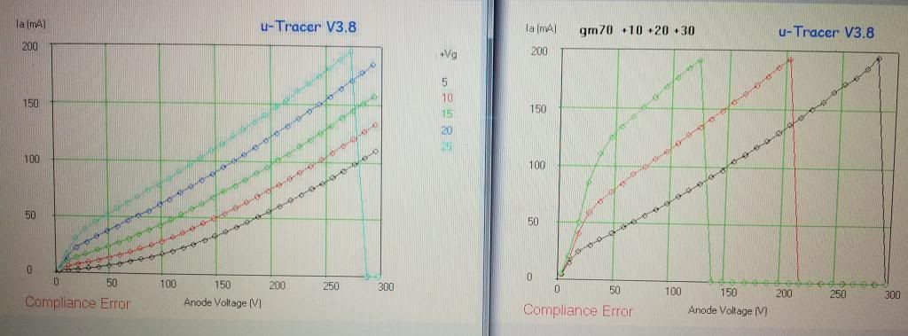
GM70
It can be seen that the two +10v lines do not exactly marry up, so we have to be imaginative about comprehending the transition from A1 curves to A2 curves.
A1

A2

Two ways of graphically displaying grid current. We start at 0v


#107
Posted: Sun Jul 28, 2013 7:47 pm
by Paul Barker
James it occurs to me you haven't adjusted for filament voltage, because if we take your Royal Blue +20v line as +10v it coincides exactly with my +10v line (itself adjusted similarly).
I believe that your curves are shaped partially as A1 curves and both these factors point to your filament cathode connection.
#108
Posted: Sun Jul 28, 2013 8:33 pm
by Paul Barker
If it is of interest from these lines it appears that even at a low 300v 100mA quiescent operating point with -10v grid bias you only need to power 12mA of grid current for 12 watts power output into a 3k load.
Should be worth a try.
#109
Posted: Sun Jul 28, 2013 10:25 pm
by James
Though I had referenced the uTracer heater circuit to the positive side of the filament, may not have though. Will check and re run during the week.
James.
#110
Posted: Mon Jul 29, 2013 8:00 am
by Paul Barker
James wrote:Though I had referenced the uTracer heater circuit to the positive side of the filament, may not have though. Will check and re run during the week.
James.
therefore you have affected the bias by 10v and not taken it into account. So your trace is -5v 0v +5v +10v +15v.
I didn't have sufficient power low ohms resistors to split the filament to middle for diddle so I have had to state the adjustment factor, but I have used the + and the - 10v facility to my advantage. I have worked on the original picture in paint to make it look better. That'll do for now.
#111
Posted: Mon Jul 29, 2013 10:21 am
by James
Paul,
From your pics you do have a symmetrical bench supply. You could go +/- 10v and reference the uTracer to the center 0v. The trends would then be correct. No resistors required.
James.
#112
Posted: Mon Jul 29, 2013 11:12 am
by Paul Barker
I wasn't sure of the centre of the bench supply was grounded and what the grounding of the cathode connection in the uTracer is. Might get ground currents. That's why I kept it floating. If the centre of the bench supply is not grounded but floating no problem. I suppose I should have tested it, but just seemed easier to work as if it can't be trusted.
Although this is relative to other valves not the GM70, I had to heat that with a floating laptop power supply. the top bench supply only does 2 amps the bottom one 1 amp.
For testing DHT's I may just sort out a powerful centre tapped secondary of 20v and turn down on the variac for lower requirements.
But I don't have much of an issue calculating out the cathode potential, in this instance the ability to go to +10v on the negative trace is an advantage. It is good too that the new GUI works from 0 volts so we can go 0 -5 -10.... instead of -1 -6 -11.....
Liking the new GUI but it's taking me a while to become reliable in use of it. I need to document what happens when and let Ronald know in case it is not just me.
#113
Posted: Mon Jul 29, 2013 11:27 am
by James
Sure you are aware but Never connect the uTracer cathode connection to anything when testing DHT's with an external supply. Use one of the heater connections. This is covered in the manual but thought I would mention it in case.
James.
#114
Posted: Mon Jul 29, 2013 11:37 am
by Paul Barker
Oops

Edit. turns out this was an OK practice.
"The situation is different when an external heater supply is used which is electrically floating with respect to the uTracer. In that case the cathode connection has to be connected to one of the heater connections on the tube (Fig. 23.2D). "
#115
Posted: Mon Jul 29, 2013 2:52 pm
by Paul Barker
I have damaged the Anode supply in the uTracer. Can't see the fault visually.
I decided to trace a CV 57 and the current it drew was very great, suddenly there was a big dip in my bench supply which was heating the valve as something in the uTracer took current. since when the anode side is crippled, the capacitor charges up to correct voltage but a test on a 340 ohm dummy load reads the wrong current. the screen side reads the correct current.
I have asked Ronald for help.
The CV57 was the problem it was taking current at a fast increasing rate and I don't think the uTracer ever expected such a bashing. we will have to beware of this.
the fuses are intact.
#116
Posted: Mon Jul 29, 2013 3:16 pm
by Paul Barker
CV57 has a peak anode current of 5 amps.
Woops!
it pulled current faster than expected and overtook the protective features of the UTracer.
I was only tracing it because I seem to remember a valve supplier once listed them as "like a PX25 triode connected" as a sales method. Yer right! Well we found out that was a lie.
CV 57 not for audio!
Hope you all appreciate this sacrifice!
A tip for my fellow uTracer owners. If you see the trace head for the sky in quick succession without requiring much voltage pull the power on the uTracer. I can tell you the rapidity of current draw was astonishing. When you look at the valves job in the above link you will comprehend.
I swear they used to try to sell it as an alternative to the PX25. not on your nelly.
#117
Posted: Mon Jul 29, 2013 3:36 pm
by Paul Barker
The uTracer met the Terminator today, seen here lying in state together. the funeral will be held at 4 oclock on Friday at the Crematorium.

Unless it is a simple matter of replacing the MJE350's!
#118
Posted: Mon Jul 29, 2013 4:03 pm
by James
[quote="Paul Barker"]The uTracer met the Terminator today, seen here lying in state together. the funeral will be held at 4 oclock on Friday at the Crematorium.
Unless it is a simple matter of replacing the MJE350's
I swear they said it would be like a PX25! I never checked!
Wally.
a really beautiful valve I so wanted it to be a PX25 in disguise. But the bias of it was in another room.
I think it went past the 200ma in less than 50v.
well the world hasn't got curves for it, and they aren't going to get them either! Now we know why the data isn't available, the country is littered with broken tube testers of those who tried!
#120
Posted: Mon Jul 29, 2013 4:14 pm
by pre65
I hope it is repairable Paul.
Otherwise we shall have to have a whip round for you to get the newest version.
